
- 1【SD】Stable Diffusion 问题_文生图提示词框没了
- 2command a expects \ followed by text
- 3Prompt提示词工程构建指南_提示词 prom
- 4Linux命令 —— sed和awk_linux sed -i替换
- 5chatGPT的prompt技巧
- 6qlaber 中放置图片_如何在设计中使用透明度?
- 7算法#16--B树完整代码Java实现_代码实现b-树的输出
- 8ACL2022 | 关系抽取和NER等论文分类整理_few-shot class-incremental learning for named enti
- 9AI帮忙做论文笔记——高端Prompt技巧——chatGPT时代背景下文献阅读新范式_阅读论文的prompt
- 102024年3月更新,10个AI绘画工具推荐
RK3288 Android 7.1 mipi副屏无法读取屏ID_mipi android7.1 mipi_dsi_dcs_write
赞
踩
一、整体思路
手上有个产品需要兼容一个新的Mipi副屏,兼容的方法跟 RK3399 Android 7.1 MIPI副屏兼容 一样,都是在uboot阶段通过将读取到的屏ID与DTS中的值就行比较,如果不相同就将其他的panel节点的status值修改为disabled,只留一个status为okay的Panel节点。最后kernel阶段就会加载status为okay的panel。
该方法最关键的部分就是读取panel的ID寄存器,只有能成功读取到屏ID,才能区分新旧屏。
二、uboot 读取屏ID
1、方法
询问屏厂商获取屏ID寄存器地址,直接通过dsi的io接口读取。我这里的新屏的ID寄存器地址是0xda
- panel:panel@0 {
- compatible = "simple-panel-dsi";
- .........
- ..............
-
- num = <0>;
- id = [93];
- id-reg = <0xda>;
-
- panel-init-sequence = [
- 15 00 02 E0 00
- 15 00 02 E1 93
- 15 00 02 E2 65
- 15 00 02 E3 F8
- 15 00 02 80 01
- 15 00 02 E0 01
- 15 00 02 00 00
- 15 00 02 01
- ..............
- ..............

2、代码实现
rockchip_dsi_panel.c
-
- static int rockchip_dsi_panel_getId(struct display_state *state)
- {
- struct panel_state *panel_state = &state->panel_state;
- struct rockchip_dsi_panel *panel = panel_state->private;
- u8 *buf;
- u8 mid[3];
- int reg,g_mipi_id;
- u8 max_size[2];
- int i,len,ret = -1;
- int count = 3;
- len = panel->id->len;
- buf = malloc(sizeof(char) * len);
-
-
- //读屏ID前要将屏使能脚和复位脚拉高
- fdtdec_set_gpio(&panel->enable_gpio, 1);
- if (panel->delay_prepare)
- msleep(panel->delay_prepare);
-
- fdtdec_set_gpio(&panel->reset_gpio, 0);
- if (panel->delay_reset)
- msleep(panel->delay_reset);
-
- if (panel->delay_init)
- msleep(panel->delay_init);
-
- while(count>0){
- if(len > 1){
- max_size[0] = len;
- ret = mipi_dsi_set_maximum_return_packet_size(state, max_size,1);
- }
-
-
- //通过mipi_dsi_dcs_read接口读取屏ID
- ret = mipi_dsi_dcs_read(state,panel->id_reg, buf,len);
- if(ret != 0){
- msleep(5);
- }
- count --;
- }
-
- if(ret == 0)//ret == 0 证明读到了寄存器的id
- for(i = 0; i < len; i++){
- dbg("read buf id[%d] = %x,panel target id[%d] = %x\n", i, *(buf + i), i, *(panel->id->buf + i));
- if(*(buf + i) != *(panel->id->buf + i))
- return -1;
- }else{
- dbg("read panel(num = %d) timeout or no response\n",panel->num);
- if(panel->num == 1)
- panel_state->num = 1; //panel->num
- return -1;
- }
- panel_state->num = panel->num; //panel_state->num 被当作是连接的副屏编号
- return 0;
- }
其中最关键的是io接口的调用
- //通过mipi_dsi_dcs_read接口读取屏ID
- ret = mipi_dsi_dcs_read(state,panel->id_reg, buf,len);
通过代码追溯,其最终的调用是
-
- static inline void dsi_write(struct dw_mipi_dsi *dsi, u32 reg, u32 val)
- {
- writel(val, dsi->base + reg);
- }
3、编译烧录验证,出现问题
通过串口打印的log发现,执行mipi_dsi_dcs_read接口发现dsi无法正常通信,报错截图如下:

看Log直接报:failed to write cmd
4、问题排查
前面提到,在读屏ID前要将屏使能脚和复位脚拉高,可以先验证这个是否正常。验证方法可以在代码set high后写一个循环,让uboot卡在那里,然后用万用表检测。
像这样:
- static int rockchip_dsi_panel_getId(struct display_state *state)
- {
- 。............
- ............
-
- fdtdec_set_gpio(&panel->enable_gpio, 1); //gpio_direction_output(GPIO_BANK7 | GPIO_A2, 1);
- if (panel->delay_prepare)
- msleep(panel->delay_prepare);
-
- fdtdec_set_gpio(&panel->reset_gpio, 0); //gpio_direction_output((GPIO_BANK3 | GPIO_B4), 1);
- if (panel->delay_reset)
- msleep(panel->delay_reset);
-
- if (panel->delay_init)
- msleep(panel->delay_init);
-
- while(1); //卡住
-
- ..................
烧录验证,使用万用表测,发现使能脚能拉高,但是复位脚显示是0V。那就找到问题所在了。
uboot阶段无法控制gpio pin的电平,可以先检查这个引脚是否在其他地方被占用了。本着从这个角度思考,我检查DTS中是否其他地方也配置了这个gpio,但grep了后发现并没有。
那就换个角度排查:是否被复用为其他function了。
5、io读取gpio寄存器
为了检查一下复位引脚的gpio的复用情况,可以使用RK提供的io工具读取相关的gpio寄存器,结合TRM手册,检查寄存器相关的bit的值,就可以知道复用情况了。
按照下面步骤一步一步来:
5.1 打开原理图,查找复位脚的gpio编号

可以看到,复位脚的gpio编号就是:GPIO3_B4
5.2 打开rk3288的TRM手册
搜 gpio3b4

可以看到,gpio3b4的function由寄存器的第8bit控制,当该bit设为0时,function为gpio;设为1时,function为flash0_cle。得到了这些关键信息,下面我们就需要读取该寄存器第8bit的值到底是多少。
往上翻滚一下手册,就可以看到:

可以得知,该寄存器的基地址名称为"GRF",还有就是偏移量为0x0024。
就差基地址了!!!!
在TRM中搜 GRF
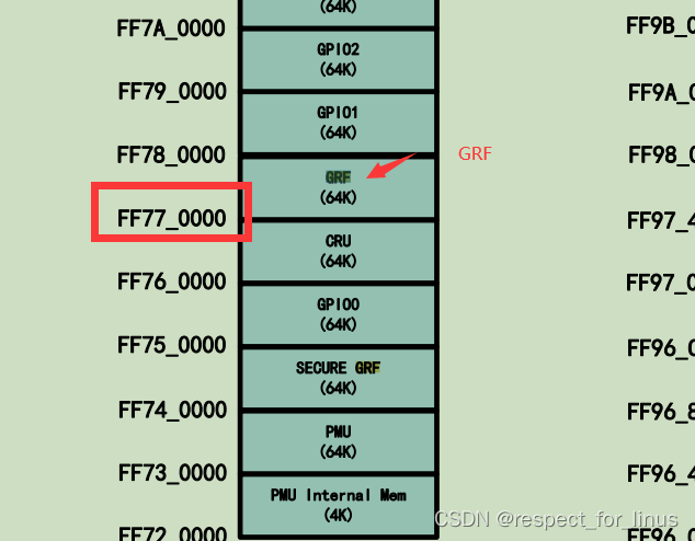
可以得知,GRF 的基地址为0xff770000.
因此,gpio3b4的寄存器完整地址为:0xff770000 + 0x0024 = 0xff770024.
走到这一步,已经搞定一半了。接一下只需要在头文件把rk的io工具打开,烧录验验证一下。
5.3 打开io工具
- diff --git a/include/configs/rk_default_config.h
- b/include/configs/rk_default_config.h
- index 9852917d4f..305de26347 100755
- --- a/include/configs/rk_default_config.h
- +++ b/include/configs/rk_default_config.h
- @@ -304,7 +304,7 @@
- /* rk io command tool */
- -#undef CONFIG_RK_IO_TOOL
- +#define CONFIG_RK_IO_TOOL
5.4 设置bootdelay
- diff --git a/common/autoboot.c b/common/autoboot.c
- index c27cc2c751..fe28adb2fd 100644
- --- a/common/autoboot.c
- +++ b/common/autoboot.c
- @@ -146,6 +146,7 @@ static int abortboot_normal(int bootdelay)
- {
- int abort = 0;
- unsigned long ts;
- + bootdelay = 3; //此处添加时间可自由定义,单位:秒
- #ifdef CONFIG_MENUPROMPT
- printf(CONFIG_MENUPROMPT);
目的就为了方便进入uboot环境调试
5.5 编译烧录刷uboot.img,io读取寄存器
make distclean 后编译,将生成的uboot.img进行烧录
进入uboot环境:
输入命令 io -4 -r 0xff770024
读取结果如下:
- rkboot # io -4 -r 0xff770024
- 0xff770024: 00005559
00005559 转换为二进制为:0001 0101 1011 0111
可以得知,gpio3b4的寄存器的第8bit值为1,结合前面的分析可知,值为1,function为flash0_cle。显然,复位脚一直拉不高的原因找到了。
5.6 查看寄存器写入规则
查看TRM,了解该寄存器的写入规则,如下图:

根据Description,大概的意思就是,bit0~15的值能否写入是由bit16~31控制。就拿我要将gpio3b4寄存器的第8bit来说,如果要在第8bit写入0,生效的前提是该寄存器的第24bit置1。
所以,根据上面所讲,要将屏复位脚的function选为GPIO,该往寄存器写入: 0x1000000
0x1000000 转为二进制为:0001 0000 0000 0000 0000 0000 0000 (第8bit为0,第24bit为1)
5.7 代码实现
- static int rockchip_dsi_panel_getId(struct display_state *state)
- {
- ...................
-
- writel(0x1000000,0xff770024); //使用writel函数写入
-
- fdtdec_set_gpio(&panel->enable_gpio, 1); //gpio_direction_output(GPIO_BANK7 | GPIO_A2, 1);
- if (panel->delay_prepare)
- msleep(panel->delay_prepare);
-
- fdtdec_set_gpio(&panel->reset_gpio, 0); //gpio_direction_output((GPIO_BANK3 | GPIO_B4), 1);
- if (panel->delay_reset)
- msleep(panel->delay_reset);
-
- ........................
5.8 编译烧录刷uboot.img,验证
进入uboot 环境,重新读取寄存器
输入 io -4 -r 0xff770024
结果如下:
- rkboot # io -4 -r 0xff770024
- 0xff770024: 00005459
0x5459 转为二进制:0101 0100 0101 1001
可以看到第8bit已经变为0
看串口打印的log,如下:
- final DSI-Link bandwidth: 800 Mbps x 2
- ---liyj--enter dw_mipi_dsi_init
- ---liyj--- __func__ : rockchip_dsi_panel_parse_dt enable_gpio->gpio = 1794
- ---liyj--- __func__ : rockchip_dsi_panel_parse_dt reset_gpio->gpio = 780
- DSI-READ: dts id reg = 0xda
-
- DSI-READ: dts id[0] = 93
-
- ---liyj--- FILE : drivers/video/rockchip_dsi_panel.c enter func : rockchip_dsi_panel_parse_cmds LINE : 94
- rockchip_dsi_panel_parse_cmds: total_len=978, cmd_cnt=196
- sssss __LINE_ : 420
- ---liyj--- __func__ : rockchip_dsi_panel_prepare reset_gpio num = 780
- ---liyj--- __func__ : rockchip_dsi_panel_prepare enable_gpio num = 1794
- ---liyj---File:drivers/video/rockchip_mipi_dsi.c Enter func : mipi_dsi_dcs_read Line : 187
- ---liyj---msg->rx_len == 1
- ---liyj---File:drivers/video/rockchip_mipi_dsi.c Enter func : mipi_dsi_dcs_read Line : 187
- ---liyj---msg->rx_len == 1
- ---liyj---File:drivers/video/rockchip_mipi_dsi.c Enter func : mipi_dsi_dcs_read Line : 187
- ---liyj---msg->rx_len == 1
- DSI-READ: read buf id[0] = 93,panel target id[0] = 93
-
- DSI-READ: dsi find panel id
可以看到能正常读取屏ID了,屏也能正常亮起来

