
- 1CF1105D-Kilani and the Game-(多向bfs)
- 2Unity七世界坐标系跟自身坐标系_世界坐标移动和自身坐标移动的区别
- 3python androidhelper 播放 音频_Android中使用AudioManager实现按键录音并保存以及点击播放功能...
- 4基于ERNIE3.0模型对小红书评论进行句子级情感分析_ernie模型进行文本分析
- 5Studio One6.5最新版本新增了对Linux的支持_ubuntu studio one
- 6GTX的64B66B编码(高速收发器十九)_rxheader[2:0]
- 7【Stable Diffusion】:SDXL1.0大模型的发布给SD带来全新的使用体验_sdxl大模型
- 8哈工大机器学习实验二逻辑回归(牛顿法、梯度下降)_哈工大机器学习实验2
- 9git rebase 过程中出现 warning: could not read ‘.git/rebase-merge/head-name‘: No such file or directory_git rebase 时 no such file or directory怎么解决
- 10内卷对于2022是一种无奈,也是一种修行_内卷 2022年
Linux SPI 驱动分析(1)— 结构框架_spi transfer
赞
踩
目录
3.1、spi_controller (spi_master)
SPI 属于高速串行全双工的接口,在 SoC 中广泛存在,关于更多 SPI 的内容可以参考《STM32F103ZET6 — SPI》,这里介绍了关于 SPI 的一些基本内容。
本章主要分析 Linux SPI 驱动框架部分。
SPI 和 platform 一样(Linux设备模型(5) — platform bus/device/driver),属于总线的一类,所以他们类似,不过 SPI 有他自己的框架,我们依然从数据结构和相关的 API 入手,着重分析 SPI 相关的架构。
Linux SPI 驱动结构中,将 SPI 相关的驱动分为了几部分:
1、SPI 主机以及主机驱动:SoC 的 SPI Controller 部分的驱动
2、SPI 外设驱动描述:比如 SPI Flash 驱动
3、SPI 从设备描述:比如 SPI Flash 设备
4、SPI 传输层描述:spi_transfer 和 spi_message 组成
1、总线互联拓扑结构
1.1、硬件拓扑
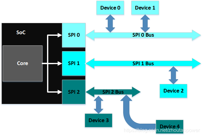
首先需要明确的是,硬件上来说,对于一款 SoC 来说,一般的,都会集成不止一路 SPI Controller(比如,SPI_0/SPI_1/SPI_2),用于控制不同的外设;而 SPI 是一种总线规范,每一路 SPI 都可以接 N 个不同的外设,通过 CS 片选信号,来选择具体与哪一个连接到这个 SPI 总线的设备通信;总线拓扑结构如下:
1.2、软件抽象
软件上,对硬件进行了合理的抽象:
1、spi_master(spi_controller):对 SoC 的 SPI 控制器的抽象
2、spi_bus_type:spi 的 bus_type,代表了硬件上的 SPI Bus
3、spi_device:spi 从设备
4、spi_driver:spi 具体设备的驱动
2、SPI 软件驱动层次
首先需要明确的一点是,SPI 主机控制器部分是整个 SPI 系统的核心存在,它并不属于 SPI 下的 bus、device、drvier 这一组结构,因为他并不是挂接到 bus 上的 device,更不是对应挂接在 bus 上 device 的 driver,而是相对独立的一个存在,所以 SPI 控制器部分,是连接到 platform 下的,并执行 platform 的 probe;
注:这里可能会不好理解,因为做过单片机的朋友都知道,单片机上的 SPI 驱动,其实就是按照时序去配置寄存器,其实就是对 SPI 控制器的操作,这就是单片机上的 driver,在 Linux driver 结构下,这个 driver 并不单单的指代对控制器的寄存器配置的过程,而是将其抽象到了一个 deivce 对应到一个实际 driver 的这个角度。所以在这里,主机控制器的抽象其实在内核中是属于一个单独的 device,所以你可以把它挂接到 platform_device 上,并套用 platform 这套东西;
可以看到结构如上图所示,比如一个 SPI Flash 它就属于 spi_device 的范畴,针对这个 SPI Flash 的驱动具体业务,就属于 spi_driver 的范畴,而 SPI 主机控制器,只是提供了一组操作的通道,可以属于 platform device 的范畴。
3、数据结构
3.1、spi_controller (spi_master)
Linux driver 中,最新的内核代码中使用 spi_controller (以前是 spi_master 结构)来描述一个 SPI 的控制器,为了兼容以前的代码,直接:
#define spi_master spi_controller所以我们直接看最新的定义 spi_controller,他在 include/linux/spi/spi.h:
- struct spi_controller {
- struct device dev;
-
- struct list_head list;
-
- /* other than negative (== assign one dynamically), bus_num is fully
- * board-specific. usually that simplifies to being SOC-specific.
- * example: one SOC has three SPI controllers, numbered 0..2,
- * and one board's schematics might show it using SPI-2. software
- * would normally use bus_num=2 for that controller.
- */
- s16 bus_num;
-
- /* chipselects will be integral to many controllers; some others
- * might use board-specific GPIOs.
- */
- u16 num_chipselect;
-
- /* some SPI controllers pose alignment requirements on DMAable
- * buffers; let protocol drivers know about these requirements.
- */
- u16 dma_alignment;
-
- /* spi_device.mode flags understood by this controller driver */
- u16 mode_bits;
-
- /* bitmask of supported bits_per_word for transfers */
- u32 bits_per_word_mask;
- #define SPI_BPW_MASK(bits) BIT((bits) - 1)
- #define SPI_BIT_MASK(bits) (((bits) == 32) ? ~0U : (BIT(bits) - 1))
- #define SPI_BPW_RANGE_MASK(min, max) (SPI_BIT_MASK(max) - SPI_BIT_MASK(min - 1))
-
- /* limits on transfer speed */
- u32 min_speed_hz;
- u32 max_speed_hz;
-
- /* other constraints relevant to this driver */
- u16 flags;
- #define SPI_CONTROLLER_HALF_DUPLEX BIT(0) /* can't do full duplex */
- #define SPI_CONTROLLER_NO_RX BIT(1) /* can't do buffer read */
- #define SPI_CONTROLLER_NO_TX BIT(2) /* can't do buffer write */
- #define SPI_CONTROLLER_MUST_RX BIT(3) /* requires rx */
- #define SPI_CONTROLLER_MUST_TX BIT(4) /* requires tx */
-
- #define SPI_MASTER_GPIO_SS BIT(5) /* GPIO CS must select slave */
-
- /* flag indicating this is an SPI slave controller */
- bool slave;
-
- /*
- * on some hardware transfer / message size may be constrained
- * the limit may depend on device transfer settings
- */
- size_t (*max_transfer_size)(struct spi_device *spi);
- size_t (*max_message_size)(struct spi_device *spi);
-
- /* I/O mutex */
- struct mutex io_mutex;
-
- /* lock and mutex for SPI bus locking */
- spinlock_t bus_lock_spinlock;
- struct mutex bus_lock_mutex;
-
- /* flag indicating that the SPI bus is locked for exclusive use */
- bool bus_lock_flag;
-
- /* Setup mode and clock, etc (spi driver may call many times).
- *
- * IMPORTANT: this may be called when transfers to another
- * device are active. DO NOT UPDATE SHARED REGISTERS in ways
- * which could break those transfers.
- */
- int (*setup)(struct spi_device *spi);
-
- /* bidirectional bulk transfers
- *
- * + The transfer() method may not sleep; its main role is
- * just to add the message to the queue.
- * + For now there's no remove-from-queue operation, or
- * any other request management
- * + To a given spi_device, message queueing is pure fifo
- *
- * + The controller's main job is to process its message queue,
- * selecting a chip (for masters), then transferring data
- * + If there are multiple spi_device children, the i/o queue
- * arbitration algorithm is unspecified (round robin, fifo,
- * priority, reservations, preemption, etc)
- *
- * + Chipselect stays active during the entire message
- * (unless modified by spi_transfer.cs_change != 0).
- * + The message transfers use clock and SPI mode parameters
- * previously established by setup() for this device
- */
- int (*transfer)(struct spi_device *spi,
- struct spi_message *mesg);
-
- /* called on release() to free memory provided by spi_controller */
- void (*cleanup)(struct spi_device *spi);
-
- /*
- * Used to enable core support for DMA handling, if can_dma()
- * exists and returns true then the transfer will be mapped
- * prior to transfer_one() being called. The driver should
- * not modify or store xfer and dma_tx and dma_rx must be set
- * while the device is prepared.
- */
- bool (*can_dma)(struct spi_controller *ctlr,
- struct spi_device *spi,
- struct spi_transfer *xfer);
-
- /*
- * These hooks are for drivers that want to use the generic
- * controller transfer queueing mechanism. If these are used, the
- * transfer() function above must NOT be specified by the driver.
- * Over time we expect SPI drivers to be phased over to this API.
- */
- bool queued;
- struct kthread_worker kworker;
- struct task_struct *kworker_task;
- struct kthread_work pump_messages;
- spinlock_t queue_lock;
- struct list_head queue;
- struct spi_message *cur_msg;
- bool idling;
- bool busy;
- bool running;
- bool rt;
- bool auto_runtime_pm;
- bool cur_msg_prepared;
- bool cur_msg_mapped;
- struct completion xfer_completion;
- size_t max_dma_len;
-
- int (*prepare_transfer_hardware)(struct spi_controller *ctlr);
- int (*transfer_one_message)(struct spi_controller *ctlr,
- struct spi_message *mesg);
- int (*unprepare_transfer_hardware)(struct spi_controller *ctlr);
- int (*prepare_message)(struct spi_controller *ctlr,
- struct spi_message *message);
- int (*unprepare_message)(struct spi_controller *ctlr,
- struct spi_message *message);
- int (*slave_abort)(struct spi_controller *ctlr);
-
- /*
- * These hooks are for drivers that use a generic implementation
- * of transfer_one_message() provied by the core.
- */
- void (*set_cs)(struct spi_device *spi, bool enable);
- int (*transfer_one)(struct spi_controller *ctlr, struct spi_device *spi,
- struct spi_transfer *transfer);
- void (*handle_err)(struct spi_controller *ctlr,
- struct spi_message *message);
-
- /* Optimized handlers for SPI memory-like operations. */
- const struct spi_controller_mem_ops *mem_ops;
-
- /* gpio chip select */
- int *cs_gpios;
-
- /* statistics */
- struct spi_statistics statistics;
-
- /* DMA channels for use with core dmaengine helpers */
- struct dma_chan *dma_tx;
- struct dma_chan *dma_rx;
-
- /* dummy data for full duplex devices */
- void *dummy_rx;
- void *dummy_tx;
-
- int (*fw_translate_cs)(struct spi_controller *ctlr, unsigned cs);
- };

源码中,注释写的非常详细,我们根据结构体的注释能够大致的知道他的含义,这里仅仅看几个关键的成员,其他成员用到的时候,加以解释:
dev:spi_controller 是一个 device,所以包含了一个 device 的实例,设备模型使用
list:链接到全局的 spi_controller list
bus_num:spi bus 的编号,比如某 SoC有3个 SPI 控制,那么这个结构描述的是第几个
num_chipselect:片选数量,决定该控制器下面挂接多少个SPI设备,从设备的片选号不能大于这个数量
mode_bits:SPI 控制器支持的 slave 的模式
min_speed_hz/max_speed_hz:最大最小速率
slave:是否是 slave
(*setup):主要设置SPI控制器和工作方式、clock等
(*transfer):添加消息到队列的方法。这个函数不可睡眠。它的职责是安排发生的传送并且调用注册的回调函 complete()。这个不同的控制器要具体实现,传输数据最后都要调用这个函数
(*cleanup):在spidev_release函数中被调用,spidev_release被登记为spi dev的release函数
3.2、spi_device
spi_device 用于描述一个挂接到 SPI 总线上的一个设备,他的结构是:
- struct spi_device {
- struct device dev;
- struct spi_controller *controller;
- struct spi_controller *master; /* compatibility layer */
- u32 max_speed_hz;
- u8 chip_select;
- u8 bits_per_word;
- u16 mode;
- #define SPI_CPHA 0x01 /* clock phase */
- #define SPI_CPOL 0x02 /* clock polarity */
- #define SPI_MODE_0 (0|0) /* (original MicroWire) */
- #define SPI_MODE_1 (0|SPI_CPHA)
- #define SPI_MODE_2 (SPI_CPOL|0)
- #define SPI_MODE_3 (SPI_CPOL|SPI_CPHA)
- #define SPI_CS_HIGH 0x04 /* chipselect active high? */
- #define SPI_LSB_FIRST 0x08 /* per-word bits-on-wire */
- #define SPI_3WIRE 0x10 /* SI/SO signals shared */
- #define SPI_LOOP 0x20 /* loopback mode */
- #define SPI_NO_CS 0x40 /* 1 dev/bus, no chipselect */
- #define SPI_READY 0x80 /* slave pulls low to pause */
- #define SPI_TX_DUAL 0x100 /* transmit with 2 wires */
- #define SPI_TX_QUAD 0x200 /* transmit with 4 wires */
- #define SPI_RX_DUAL 0x400 /* receive with 2 wires */
- #define SPI_RX_QUAD 0x800 /* receive with 4 wires */
- #define SPI_CS_WORD 0x1000 /* toggle cs after each word */
- int irq;
- void *controller_state;
- void *controller_data;
- char modalias[SPI_NAME_SIZE];
- const char *driver_override;
- int cs_gpio; /* chip select gpio */
-
- /* the statistics */
- struct spi_statistics statistics;
-
- /*
- * likely need more hooks for more protocol options affecting how
- * the controller talks to each chip, like:
- * - memory packing (12 bit samples into low bits, others zeroed)
- * - priority
- * - chipselect delays
- * - ...
- */
- };
他的成员相对 spi_controller 要少很多:
dev:device 结构,设备模型使用
controller:这个 spi device 挂在那个 SPI Controller 下
max_speed_hz:通讯时钟最大频率
chip_select:片选号,每个 master 支持多个 spi_device
mode:SPI device 的模式,时钟极性和时钟相位
bits_per_word:每个通信字的字长的比特数,默认是 8
irq:使用到的中断号
modalias:设备驱动的名字
由于一个SPI总线上可以有多个SPI设备,因此需要片选号来区分它们,SPI控制器根据片选号来选择不同的片选线,从而实现每次只同一个设备通信。
spi_device的mode成员有两个比特位含义很重要。SPI_CPHA选择对数据线采样的时机,0选择每个时钟周期的第一个沿跳变时采样数据,1选择第二个时钟沿采样数据;SPI_CPOL选择每个时钟周期开始的极性,0表示时钟以低电平开始,1选择高电平开始。这两个比特有四种组合,对应SPI_MODE_0~SPI_MODE_3。
另一个比较重要的成员是bits_per_word。这个成员指定每次读写的字长,单位是比特。虽然大部分SPI接口的字长是8或者16,仍然会有一些特殊的例子。需要说明的是,如果这个成员为零的话,默认使用8作为字长。
最后一个成员并不是设备的名字,而是需要绑定的驱动的名字。
3.3、spi_driver
spi_driver 代表一个驱动,他也挂接到了 spi bus 上,与对应的 spi_device 结构进行匹配后调用 probe,他的定义是:
- struct spi_driver {
- const struct spi_device_id *id_table;
- int (*probe)(struct spi_device *spi);
- int (*remove)(struct spi_device *spi);
- void (*shutdown)(struct spi_device *spi);
- struct device_driver driver;
- };
可以看到,其实就是最简单的成员,他并不提供任何与硬件的实际交互
3.4、spi_board_info
spi_device 的板信息用 spi_board_info 结构体描述,该结构体记录着SPI外设使用的主机控制器序号、片选序号、数据比特率、SPI传输模式(即CPOL、CPHA)等。ARM Linux3.x之后的内核在改为设备树之后,不再需要在arch/arm/mach-xxx中编码SPI的板级信息了,而倾向于在SPI控制器节点下填写子节点
如果定义了这个结构,然后在调用他的 register,并会分配并新建一个对应 spi_device,他的结构如下:
- struct spi_board_info {
- /* the device name and module name are coupled, like platform_bus;
- * "modalias" is normally the driver name.
- *
- * platform_data goes to spi_device.dev.platform_data,
- * controller_data goes to spi_device.controller_data,
- * device properties are copied and attached to spi_device,
- * irq is copied too
- */
- char modalias[SPI_NAME_SIZE];
- const void *platform_data;
- const struct property_entry *properties;
- void *controller_data;
- int irq;
-
- /* slower signaling on noisy or low voltage boards */
- u32 max_speed_hz;
-
-
- /* bus_num is board specific and matches the bus_num of some
- * spi_controller that will probably be registered later.
- *
- * chip_select reflects how this chip is wired to that master;
- * it's less than num_chipselect.
- */
- u16 bus_num;
- u16 chip_select;
-
- /* mode becomes spi_device.mode, and is essential for chips
- * where the default of SPI_CS_HIGH = 0 is wrong.
- */
- u16 mode;
-
- /* ... may need additional spi_device chip config data here.
- * avoid stuff protocol drivers can set; but include stuff
- * needed to behave without being bound to a driver:
- * - quirks like clock rate mattering when not selected
- */
- };
他成员的内容几乎和 spi_device 一致,不再多说;
3.5、spi_transfer
spi_transfer 代表一个读写缓冲对,包含接收缓冲区及发送缓冲区,其实,spi_transfer的发送是通过构建spi_message实现,通过将spi_transfer中的链表transfer_list链接到spi_message中的transfers,再以spi_message形势向底层发送数据。每个spi_transfer都可以对传输的一些参数进行设置,使得master controller按照它要求的参数进行数据发送
- struct spi_transfer {
- /* it's ok if tx_buf == rx_buf (right?)
- * for MicroWire, one buffer must be null
- * buffers must work with dma_*map_single() calls, unless
- * spi_message.is_dma_mapped reports a pre-existing mapping
- */
- const void *tx_buf;
- void *rx_buf;
- unsigned len;
-
- dma_addr_t tx_dma;
- dma_addr_t rx_dma;
- struct sg_table tx_sg;
- struct sg_table rx_sg;
-
- unsigned cs_change:1;
- unsigned tx_nbits:3;
- unsigned rx_nbits:3;
- #define SPI_NBITS_SINGLE 0x01 /* 1bit transfer */
- #define SPI_NBITS_DUAL 0x02 /* 2bits transfer */
- #define SPI_NBITS_QUAD 0x04 /* 4bits transfer */
- u8 bits_per_word;
- u16 delay_usecs;
- u32 speed_hz;
- u16 word_delay;
-
- struct list_head transfer_list;
- };
tx_buf:发送缓冲区,要写入设备的数据(必须是dma_safe),或者为NULL
rx_buf:接收缓冲区,要读取的数据缓冲(必须是dma_safe),或者为NULL
len:缓冲区长度,tx和rx的大小(字节数)。这里不是指它的和,而是各自的长度,它们总是相等的
tx_dma:如果spi_message.is_dma_mapped是真,这个是tx的dma地址
rx_dma:如果spi_message.is_dma_mapped是真,这个是rx的dma地址
cs_change:1 :当前spi_transfer发送完成之后重新片选。影响此次传输之后的片选。指示本次transfer结束之后是否要重新片选并调用setup改变设置。这个标志可以减少系统开销
bits_per_word:每个字长的比特数,0代表使用spi_device中的默认值 8
delay_usecs:发送完成一个spi_transfer后延时时间,此次传输结束和片选改变之间的延时,之后就会启动另一个传输或者结束整个消息
speed_hz:通信时钟。如果是0,使用默认值
transfer_list:用于链接到spi_message,用来连接的双向链接节点
控制器驱动会先写入tx 的数据,然后读取同样长度的数据。长度指示是 len
如果tx_buff是空指针,填充rx_buff的时候会输出0(为了产生接收的时钟),如果rx_buff是NULL,接收到的数据将被丢弃
只有 len 长度的数据会被输出和接收
3.6、spi_message
spi_message 代表 spi 消息,由多个spi_transfer段组成。
spi_message用来原子的执行spi_transfer表示的一串数组传输请求。
这个传输队列是原子的,这意味着在这个消息完成之前不会有其它消息占用总线。
消息的执行总是按照FIFO的顺序。
向底层提交spi_message的代码要负责管理它的内存空间。未显示初始化的内存需要使用0来初始化。
- struct spi_message {
- struct list_head transfers;
-
- struct spi_device *spi;
-
- unsigned is_dma_mapped:1;
-
- /* REVISIT: we might want a flag affecting the behavior of the
- * last transfer ... allowing things like "read 16 bit length L"
- * immediately followed by "read L bytes". Basically imposing
- * a specific message scheduling algorithm.
- *
- * Some controller drivers (message-at-a-time queue processing)
- * could provide that as their default scheduling algorithm. But
- * others (with multi-message pipelines) could need a flag to
- * tell them about such special cases.
- */
-
- /* completion is reported through a callback */
- void (*complete)(void *context);
- void *context;
- unsigned frame_length;
- unsigned actual_length;
- int status;
-
- /* for optional use by whatever driver currently owns the
- * spi_message ... between calls to spi_async and then later
- * complete(), that's the spi_controller controller driver.
- */
- struct list_head queue;
- void *state;
-
- /* list of spi_res reources when the spi message is processed */
- struct list_head resources;
- };
transfer:这个 mesage 含的 transfer 链表
spi:传输的目标设备
is_dma_mapped:spi_transfer 中 tx_dma 和 rx_dma 是否已经 mapped
complete:数据传输完成的回调函数
context:提供给complete的可选参数
actual_length:spi_message已经传输了的字节数
status:出错与否,错误时返回 errorcode
queue 、state:供controller驱动内部使用
spi_message:描述一次完整的传输,即cs信号从高->底->高的传输
spi_transfer:多个 spi_transfer 够成一个 spi_message
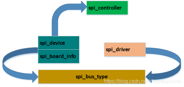
3.7、数据结构之间的关系
上面的数据结构,基本上组成了 SPI 框架的内容,在软件层次上我们将 SPI Controller,Bus,Driver,Slave Device 结构抽象为如下:
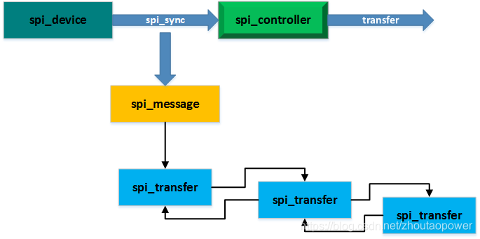
在数据发送的结构部分,内核将其抽象如下:
4、对外接口 APIs
数据结构理清楚了,暂时把 SPI Framework 看成一个黑盒子,先关心到底怎么用这个 SPI Framework,首先来看看他提供出来的接口 APIs,后面我们再来打开黑盒看看!
SPI Framework 提供的所有 APIs,几乎都可以在 include/linux/spi/spi.h 中找到,主要都是围绕着数据结构进行的,我们按照使用的流程来一步一步看看;首先先从定义注册 SPI Controller 开始入手;
1、分配 spi_controller (spi_master)
struct spi_controller *spi_alloc_master(struct device *host, unsigned int size)这个接口用于分配并返回一个 spi_controller (spi_master)结构,前面也说过,SPI 控制器部分,可以挂接到 platform 上,所以这个 API 的使用场景是 SoC 的 spi 控制器 probe 的时候,调用 spi_alloc_master 来获得一个 spi_controller,并根据 SoC 自身的资源情况,来填充 spi_controller 下的各个成员。
注意:这里传入的 *host 便是 xxx_spi_probe(struct platform_device *pdev) 中的 &pdev->dev 部分,后面的 size,可以指的是私有的数据,并且包含了 spi_controller 的实例;
2、注册 spi_controller (spi_master)
- int spi_register_controller(struct spi_controller *ctlr);
- int spi_register_master(struct spi_controller *ctlr);
在第一步的 probe 中,将分配好并且已经完成了必要初始化的 spi_controller 结构注册到内核。在这个函数中,其实是进行了一些必要的设备模型的操作和钩子函数的 check,通过后,挂接到全局的 spi_controller_list 链表上。
这里需要注意一下,由于 SoC 一般存在多个 SPI Controller,所以在资源定义的时候(不管是 DTS 还是 platform_device),这个 probe 会被调用多次,所有的 spi_controller 都挂到了 spi_controller_list 链表上。
3、分配 spi_device
分配一个并简单初始化 spi_device
struct spi_device *spi_alloc_device(struct spi_controller *ctlr);
4、添加 spi_device
将 spi_device 添加的 device 系统
int spi_add_device(struct spi_device *spi);
5、分配并添加 spi_device
这个接口是上面两个接口的结合,往指定的 spi_controller 上添加一个 spi_borad_info:
- struct spi_device *spi_new_device(struct spi_controller *ctlr,
- struct spi_board_info *chip);
6、注册 spi_driver
- #define spi_register_driver(driver) \
- __spi_register_driver(THIS_MODULE, driver)
往 SPI BUS 上添加一个 driver
7、初始化 spi_message
void spi_message_init(struct spi_message *m);用于传输之前,进行 spi_message 结构的初始化
8、添加 transfer 到指定的 spi_message
void spi_message_add_tail(struct spi_transfer *t, struct spi_message *m);将希望传输的 transfer 到指定的已经完成初始化的 spi_message;
9、初始化一个 spi_message 并添加 N 个 transfer
- void spi_message_init_with_transfers(struct spi_message *m,
- struct spi_transfer *xfers, unsigned int num_xfers)
这个接口是上面两个的合并版本,初始化一个 spi_message,并将 num_xfers 个 xfers 挂接到 spi_message 上;
10、分配 1个 spi_message 和 N 个其下的 spi_transfer
struct spi_message *spi_message_alloc(unsigned ntrans, gfp_t flags);这个接口也是一个高级版本,先分配 1 个 spi_message 和 ntrans 个 spi_transfer,并对其进行初始化,将 spi_transfer 全部挂接到 spi_message;
11、控制器 setup
int spi_setup(struct spi_device *spi);根据与 spi_device 的属性,setup 我们的 SPI Controller 的 mode 和 clock rate
12、异步传输数据
- int spi_async(struct spi_device *spi, struct spi_message *message);
- int spi_async_locked(struct spi_device *spi, struct spi_message *message);
往 spi_device 提价 spi_message 的数据
因为是异步的,一提交就立马返回了,这也就是说需要同步机制(complete 就是了)。他确保不会睡眠,使用 spinlock,可安全的在中断 handler 或其他不可休眠的代码中调用。
使用 spi_async() 需要注意的是,在complete()未返回前不要轻易访问你一提交的 spi_transfer 中的buffer。也不能释放SPI系统正在使用的buffer。一旦你的complete返回了,这些buffer就又是你的了。
13、同步传输数据
- int spi_sync(struct spi_device *spi, struct spi_message *message);
- int spi_sync_locked(struct spi_device *spi, struct spi_message *message);
同步数据传输,完成后返回,也就是说,允许睡眠,使用的是 mutex 锁,返回后,可立即访问 buffer
14、添加若干 spi_transfer 并同步传输
- int spi_sync_transfer(struct spi_device *spi, struct spi_transfer *xfers,
- unsigned int num_xfers);
这个是前面同步传输的高级版本,往一个 spi_message 中添加已经初始化好的 num_xfers 个 spi_transfer,并嗲用 spi_sync ,往 指定的 spi_device 进行数据传输,返回 0,代表完成;允许睡眠
15、同步写一次数据
int spi_write(struct spi_device *spi, const void *buf, size_t len);向指定的 spi 设备,同步写一个长为 len 的 buf 数据,注意,这里是往一个 spi_message 中填充一个 spi_transter
15、同步读一次
int spi_read(struct spi_device *spi, const void *buf, size_t len);向指定的 spi 设备,同步读一个长为 len 的 buf 数据,注意,这里是往一个 spi_message 中填充一个 spi_transter
16、同步写一次同时读一次
- /* this copies txbuf and rxbuf data; for small transfers only! */
- int spi_write_then_read(struct spi_device *spi,
- const void *txbuf, unsigned n_tx,
- void *rxbuf, unsigned n_rx);
SPI 是全双工的,这个接口是向指定的 spi 设备写入 n_tx 个数据,同时读取 n_rx 数据,接口调用允许睡眠。
注:看注释知道,这个只为小型读写专用
17、同步写一个 8-bits 命令,读 8-bits 状态
- /**
- * spi_w8r8 - SPI synchronous 8 bit write followed by 8 bit read
- * @spi: device with which data will be exchanged
- * @cmd: command to be written before data is read back
- * Context: can sleep
- *
- * Callable only from contexts that can sleep.
- *
- * Return: the (unsigned) eight bit number returned by the
- * device, or else a negative error code.
- */
-
- ssize_t spi_w8r8(struct spi_device *spi, u8 cmd);
这个接口,有点带专用性,比如你有一个 SPI Flash,他支持使用 SPI 命令配置 SPI Flash,并返回 SPI Flash 状态码的话,那么就可以使用这个接口,这个接口其实是封装了 spi_write_then_read 接口,将 cmd 写入 SPI,将 rx 的 buffer (比如 SPI Flash 收到配置 cmd 后,通过 SPI 传输了一个状态码到 SoC)返回。
17、同步写一个 8-bits 命令,读 16-bits 状态
- /**
- * spi_w8r16 - SPI synchronous 8 bit write followed by 16 bit read
- * @spi: device with which data will be exchanged
- * @cmd: command to be written before data is read back
- * Context: can sleep
- *
- * The number is returned in wire-order, which is at least sometimes
- * big-endian.
- *
- * Callable only from contexts that can sleep.
- *
- * Return: the (unsigned) sixteen bit number returned by the
- * device, or else a negative error code.
- */
-
- ssize_t spi_w8r16(struct spi_device *spi, u8 cmd);
这个接口和上面一个类似,只不过返回的是 2 个 Bytes,也就是针对对方要返回 16bits 状态的情况,不再多说。
参考文献:
https://blog.csdn.net/wuhzossibility/article/details/7832438
https://www.jianshu.com/p/60d2d5849db9
http://emb.hqyj.com/Column/Column367.htm
https://blog.csdn.net/yaolanshu_june/article/details/52356138
https://www.linuxidc.com/Linux/2012-07/64942.htm

