
热门标签
热门文章
- 14 款好用到爆的 JSON 处理工具,极大提高效率!
- 2auditd审计系统的user-space组件
- 32024 年学习 AI 路线图_人工智能学习路线
- 4Windows单机配置Kafka环境_在windows上搭建单机版的kafka来实现实时同步数据
- 5梯度提升(Gradient boosting)和GBDT
- 6CSS浮动一:div基本介绍(背景色,大小,坐标位置,溢出处理,outline,border边框)_div outline
- 7[深度学习] 计算机视觉低代码工具Supervision库使用指北_supervisionpython
- 8计算机网络——基于UDP与TCP网络编程_基于udp的tcp设计
- 9【错误记录】Android Studio 配置 AspectJ 报错 ( Failed to create Jar file C:\xxx\aspectjtools-1.8.10.jar. )
- 10MySQL的undo log日志_undolog内容读取
当前位置: article > 正文
RT-Thread基于AT32单片机的CAN应用_at32 workbench
作者:空白诗007 | 2024-06-25 08:18:24
赞
踩
at32 workbench
1 硬件电路

2 RT-Thread驱动配置
RT-Studio中没有CAN相关的图形配置,需要手动修改board.h。在board.h的末尾,增加相关的BSP配置。
- #define RT_CAN_USING_HDR
- #define BSP_USING_CAN1
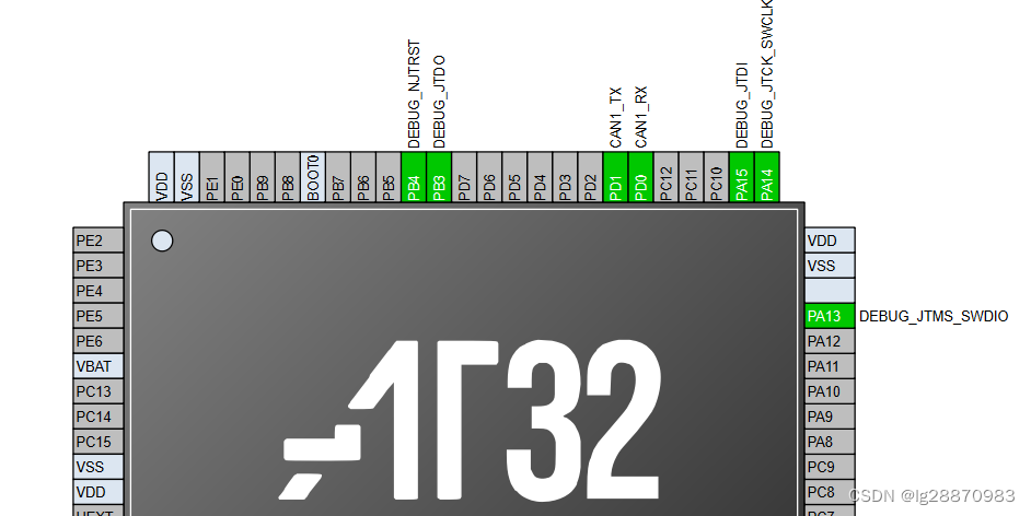
3 IO配置
at32_msp.c中的IO配置是PB9和PB10,掌上实验室V9实际采用的是PD0和PD1,需要修改CAN1相关的IO配置代码。
IO配置代码可以采用AT32_workbench生成,如下图所示。
at32a403a_wk_config.c中找到相关代码,修改RT-Studio中的at32_msp.c的相关代码,如下所示:
- void at32_msp_can_init(void *instance)
- {
- #if defined (BSP_USING_CAN1) || defined (BSP_USING_CAN2)
- gpio_init_type gpio_init_struct;
- can_type *can_x = (can_type *)instance;
-
- gpio_default_para_init(&gpio_init_struct);
- gpio_init_struct.gpio_drive_strength = GPIO_DRIVE_STRENGTH_STRONGER;
- #ifdef BSP_USING_CAN1
- if(CAN1 == can_x)
- {
- crm_periph_clock_enable(CRM_CAN1_PERIPH_CLOCK, TRUE);
- // crm_periph_clock_enable(CRM_GPIOB_PERIPH_CLOCK, TRUE);
- // crm_periph_clock_enable(CRM_IOMUX_PERIPH_CLOCK, TRUE);
- //
- // gpio_init_struct.gpio_mode = GPIO_MODE_MUX;
- // gpio_init_struct.gpio_out_type = GPIO_OUTPUT_PUSH_PULL;
- // gpio_init_struct.gpio_pull = GPIO_PULL_NONE;
- // gpio_init_struct.gpio_pins = GPIO_PINS_9;
- // gpio_init(GPIOB, &gpio_init_struct);
- // gpio_pin_remap_config(CAN1_GMUX_0010, TRUE);
- //
- // gpio_init_struct.gpio_mode = GPIO_MODE_INPUT;
- // gpio_init_struct.gpio_pull = GPIO_PULL_NONE;
- // gpio_init_struct.gpio_pins = GPIO_PINS_8;
- // gpio_init(GPIOB, &gpio_init_struct);
-
- crm_periph_clock_enable(CRM_GPIOD_PERIPH_CLOCK, TRUE);
- /* configure the CAN1 TX pin */
- gpio_init_struct.gpio_drive_strength = GPIO_DRIVE_STRENGTH_MODERATE;
- gpio_init_struct.gpio_out_type = GPIO_OUTPUT_PUSH_PULL;
- gpio_init_struct.gpio_mode = GPIO_MODE_MUX;
- gpio_init_struct.gpio_pins = GPIO_PINS_1;
- gpio_init_struct.gpio_pull = GPIO_PULL_NONE;
- gpio_init(GPIOD, &gpio_init_struct);
-
- /* configure the CAN1 RX pin */
- gpio_init_struct.gpio_drive_strength = GPIO_DRIVE_STRENGTH_STRONGER;
- gpio_init_struct.gpio_out_type = GPIO_OUTPUT_PUSH_PULL;
- gpio_init_struct.gpio_mode = GPIO_MODE_INPUT;
- gpio_init_struct.gpio_pins = GPIO_PINS_0;
- gpio_init_struct.gpio_pull = GPIO_PULL_NONE;
- gpio_init(GPIOD, &gpio_init_struct);
-
- /* GPIO PIN remap */
- gpio_pin_remap_config(CAN1_GMUX_0011, TRUE);
-
- }
- #endif
- #ifdef BSP_USING_CAN2
- if(CAN2 == can_x)
- {
- crm_periph_clock_enable(CRM_CAN2_PERIPH_CLOCK, TRUE);
- crm_periph_clock_enable(CRM_GPIOB_PERIPH_CLOCK, TRUE);
- crm_periph_clock_enable(CRM_IOMUX_PERIPH_CLOCK, TRUE);
-
- gpio_init_struct.gpio_mode = GPIO_MODE_MUX;
- gpio_init_struct.gpio_out_type = GPIO_OUTPUT_PUSH_PULL;
- gpio_init_struct.gpio_pull = GPIO_PULL_NONE;
- gpio_init_struct.gpio_pins = GPIO_PINS_6;
- gpio_init(GPIOB, &gpio_init_struct);
- gpio_pin_remap_config(CAN2_GMUX_0001, TRUE);
-
- gpio_init_struct.gpio_mode = GPIO_MODE_INPUT;
- gpio_init_struct.gpio_pull = GPIO_PULL_NONE;
- gpio_init_struct.gpio_pins = GPIO_PINS_5;
- gpio_init(GPIOB, &gpio_init_struct);
- }
- #endif
- #endif
- }
-
- void at32_msp_emac_init(void *instance)
- {
- #if defined (BSP_USING_EMAC)
- gpio_init_type gpio_init_struct;
-
- crm_periph_clock_enable(CRM_GPIOA_PERIPH_CLOCK, TRUE);
- crm_periph_clock_enable(CRM_GPIOB_PERIPH_CLOCK, TRUE);
- crm_periph_clock_enable(CRM_GPIOC_PERIPH_CLOCK, TRUE);
- crm_periph_clock_enable(CRM_GPIOD_PERIPH_CLOCK, TRUE);
- crm_periph_clock_enable(CRM_IOMUX_PERIPH_CLOCK, TRUE);
-
- gpio_pin_remap_config(EMAC_MUX, TRUE);
-
- gpio_default_para_init(&gpio_init_struct);
- gpio_init_struct.gpio_drive_strength = GPIO_DRIVE_STRENGTH_STRONGER;
- gpio_init_struct.gpio_mode = GPIO_MODE_MUX;
- gpio_init_struct.gpio_out_type = GPIO_OUTPUT_PUSH_PULL;
- gpio_init_struct.gpio_pull = GPIO_PULL_NONE;
- gpio_init_struct.gpio_pins = GPIO_PINS_2;
- gpio_init(GPIOA, &gpio_init_struct);
-
- gpio_init_struct.gpio_pins = GPIO_PINS_11 | GPIO_PINS_12 | GPIO_PINS_13;
- gpio_init(GPIOB, &gpio_init_struct);
-
- gpio_init_struct.gpio_pins = GPIO_PINS_1;
- gpio_init(GPIOC, &gpio_init_struct);
-
- gpio_init_struct.gpio_mode = GPIO_MODE_INPUT;
- gpio_init_struct.gpio_pull = GPIO_PULL_NONE;
- gpio_init_struct.gpio_pins = GPIO_PINS_1;
- gpio_init(GPIOA, &gpio_init_struct);
-
- gpio_init_struct.gpio_mode = GPIO_MODE_INPUT;
- gpio_init_struct.gpio_pull = GPIO_PULL_NONE;
- gpio_init_struct.gpio_pins = GPIO_PINS_8 | GPIO_PINS_9 | GPIO_PINS_10;
- gpio_init(GPIOD, &gpio_init_struct);
- #endif
- }

4 时钟配置
drv_can.c中给出了can的bitrate配置代码,如下所示:
- #ifdef SOC_SERIES_AT32F403A
- /* attention !!! baud calculation example: apbclk / ((ss + bs1 + bs2) * brp), ep: 120 / ((1 + 8 + 3) * 10) = 1MHz*/
- /* attention !!! default apbclk 120 mhz */
- static const struct at32_baud_rate can_baud_rate_tab[] =
- {
- {CAN1MBaud, {10 , CAN_RSAW_3TQ, CAN_BTS1_8TQ, CAN_BTS2_3TQ}},
- {CAN800kBaud, {15 , CAN_RSAW_2TQ, CAN_BTS1_7TQ, CAN_BTS2_2TQ}},
- {CAN500kBaud, {20 , CAN_RSAW_2TQ, CAN_BTS1_9TQ, CAN_BTS2_2TQ}},
- {CAN250kBaud, {40 , CAN_RSAW_2TQ, CAN_BTS1_9TQ, CAN_BTS2_2TQ}},
- {CAN125kBaud, {80 , CAN_RSAW_2TQ, CAN_BTS1_9TQ, CAN_BTS2_2TQ}},
- {CAN100kBaud, {75 , CAN_RSAW_2TQ, CAN_BTS1_13TQ, CAN_BTS2_2TQ}},
- {CAN50kBaud, {150, CAN_RSAW_2TQ, CAN_BTS1_13TQ, CAN_BTS2_2TQ}},
- {CAN20kBaud, {375, CAN_RSAW_2TQ, CAN_BTS1_13TQ, CAN_BTS2_2TQ}},
- {CAN10kBaud, {750, CAN_RSAW_2TQ, CAN_BTS1_13TQ, CAN_BTS2_2TQ}}
- };
这里要特别注意的是,所有计算是基于apbclk=120MHz。要确认RT-Studio生成的代码的时钟正确,否则需重新配置时钟或修改at32_baud_rate can_baud_rate_tab表格内容。
5 RT-Thread应用示例
- #include <rtthread.h>
- #include "rtdevice.h"
-
- #ifdef RT_USING_CAN
-
- #define CAN_DEV_NAME "can1" /* CAN 设备名称 */
-
- static struct rt_semaphore rx_sem; /* 用于接收消息的信号量 */
- static rt_device_t can_dev; /* CAN 设备句柄 */
-
- #define THREAD_PRIORITY 25
- #define THREAD_STACK_SIZE 512
- #define THREAD_TIMESLICE 5
-
- static rt_thread_t tid1 = RT_NULL;
- static volatile int running = 0;
-
- static int data_buf[10];
- static uint32_t data_cnt = 0;
-
- rt_err_t lp40_recv(uint16_t id, uint8_t *msg)
- {
- if(crc_high_first(msg,6)){
- }
- return RT_EOK;
-
- }
-
-
- /* 接收数据回调函数 */
- static rt_err_t can_rx_call(rt_device_t dev, rt_size_t size) {
- /* CAN 接收到数据后产生中断,调用此回调函数,然后发送接收信号量 */
- rt_sem_release(&rx_sem);
-
- return RT_EOK;
- }
-
- static void can_rx_thread(void *parameter) {
- int i;
- //rt_err_t res;
- struct rt_can_msg rxmsg = {0};
-
- /* 设置接收回调函数 */
- rt_device_set_rx_indicate(can_dev, can_rx_call);
-
- #ifdef RT_CAN_USING_HDR
- struct rt_can_filter_item items[5] = {
- RT_CAN_FILTER_ITEM_INIT(0x100, 0, 0, 1, 0x700, RT_NULL, RT_NULL), /* std,match ID:0x100~0x1ff,hdr 为 - 1,设置默认过滤表 */
- RT_CAN_FILTER_ITEM_INIT(0x300, 0, 0, 1, 0x700, RT_NULL, RT_NULL), /* std,match ID:0x300~0x3ff,hdr 为 - 1 */
- RT_CAN_FILTER_ITEM_INIT(0x211, 0, 0, 1, 0x7ff, RT_NULL, RT_NULL), /* std,match ID:0x211,hdr 为 - 1 */
- RT_CAN_FILTER_STD_INIT(0x486, RT_NULL, RT_NULL), /* std,match ID:0x486,hdr 为 - 1 */
- {0x555, 0, 0, 1, 0x7ff, 7,} /* std,match ID:0x555,hdr 为 7,指定设置 7 号过滤表 */
- };
- struct rt_can_filter_config cfg = {5, 1, items}; /* 一共有 5 个过滤表 */
- /* 设置硬件过滤表 */
- res = rt_device_control(can_dev, RT_CAN_CMD_SET_FILTER, &cfg);
- RT_ASSERT(res == RT_EOK);
- #endif
- int rx_count = 0;
-
- while (running) {
- /* hdr 值为 - 1,表示直接从 uselist 链表读取数据 */
- rxmsg.hdr_index = -1;
- /* 阻塞等待接收信号量 */
- if(rt_sem_take(&rx_sem, RT_WAITING_FOREVER)==RT_EOK){
- /* 从 CAN 读取一帧数据 */
- rt_device_read(can_dev, 0, &rxmsg, sizeof(rxmsg));
- /* 打印数据 ID 及内容 */
- rt_kprintf("recv %ld : id = %d, ide=%d :", ++rx_count, rxmsg.id, rxmsg.ide);
- for (i = 0; i < rxmsg.len; i++) {
- rt_kprintf(" %02x", rxmsg.data[i]);
- }
- rt_kprintf("\n");
-
-
- }
- }
- }
-
- /* 线程 1 的入口函数 */
- static void thread1_entry(void *parameter) {
- struct rt_can_msg msg = {0};
- int count = 0;
-
- msg.id = 0x123; /* ID 为 0x78 */
- msg.ide = RT_CAN_STDID; /* 标准格式 */
- //msg.ide = RT_CAN_EXTID; /* 标准格式 */
- msg.rtr = RT_CAN_DTR; /* 数据帧 */
- msg.len = 8; /* 数据长度为 8 */
- /* 待发送的 8 字节数据 */
- msg.data[0] = 0x00;
- msg.data[1] = 0x11;
- msg.data[2] = 0x22;
- msg.data[3] = 0x33;
- msg.data[4] = 0x44;
- msg.data[5] = 0x55;
- msg.data[6] = 0x66;
- msg.data[7] = 0x77;
-
-
- while(running) {
- /* 线程 1 采用低优先级运行,一直打印计数值 */
- rt_kprintf("send %d : id = %d, ide=%d :", ++count, msg.id, msg.ide);
- for(int i=0;i<msg.len;i++)
- rt_kprintf(" %02x", msg.data[i]);
- rt_kprintf("\n");
- rt_device_write(can_dev, 0, &msg, sizeof(msg));
- for(int i=0;i<100;i++){
- rt_thread_mdelay(50);
- if(!running)
- break;
- }
- }
- rt_device_close(can_dev);
- }
-
- int can_sample(int argc, char *argv[]) {
- rt_err_t res;
- rt_size_t size;
- rt_thread_t thread;
- char can_name[RT_NAME_MAX];
-
- if (argc == 2) {
- rt_strncpy(can_name, argv[1], RT_NAME_MAX);
- } else {
- rt_strncpy(can_name, CAN_DEV_NAME, RT_NAME_MAX);
- }
-
- if(running){
- rt_kprintf("can_sample is running, stop it before restart!\n can_sample_stop\n", can_name);
- return RT_ERROR;
- }
-
- /* 查找 CAN 设备 */
- can_dev = rt_device_find(can_name);
- if (!can_dev) {
- rt_kprintf("find %s failed!\n", can_name);
- return RT_ERROR;
- }
-
- running = 1;
-
- res = rt_sem_init(&rx_sem, "rx_sem", 0, RT_IPC_FLAG_FIFO);
-
- /* 以中断接收及发送方式打开 CAN 设备 */
- res = rt_device_open(can_dev, RT_DEVICE_FLAG_INT_TX | RT_DEVICE_FLAG_INT_RX);
- /* 初始化 CAN 接收信号量 */
-
-
- /* 设置 CAN 的工作模式为正常工作模式 */
- res = rt_device_control(can_dev, RT_CAN_CMD_SET_MODE, (void *)RT_CAN_MODE_NORMAL);
- //res = rt_device_control(can_dev, RT_CAN_CMD_SET_MODE, (void *)RT_CAN_MODE_LOOPBACK);
- res = rt_device_control(can_dev, RT_CAN_CMD_SET_BAUD, (void *)CAN125kBaud);
-
- RT_ASSERT(res == RT_EOK);
- /* 创建数据接收线程 */
- thread = rt_thread_create("can_rx", can_rx_thread, RT_NULL, 1024, 25, 10);
- if (thread != RT_NULL) {
- rt_thread_startup(thread);
- } else {
- rt_kprintf("create can_rx thread failed!\n");
- }
-
-
- if (size == 0) {
- rt_kprintf("can dev write data failed!\n");
- }
-
- /* 创建线程 1,名称是 thread1,入口是 thread1_entry*/
- tid1 = rt_thread_create("thread1",
- thread1_entry, RT_NULL,
- THREAD_STACK_SIZE,
- THREAD_PRIORITY, THREAD_TIMESLICE);
-
- /* 如果获得线程控制块,启动这个线程 */
- if (tid1 != RT_NULL)
- rt_thread_startup(tid1);
- else
- rt_kprintf("start can send fail\n");
-
- return res;
- }
-
- int can_sample_stop(int argc, char *argv[]) {
- if(running){
- running = 0;
- //rt_sem_release(&rx_sem);
- rt_sem_detach(&rx_sem);
- }
- return RT_EOK;
- }
- /* 导出到 msh 命令列表中 */
- MSH_CMD_EXPORT(can_sample, can device sample);
- MSH_CMD_EXPORT(can_sample_stop, can device sample stop);
-
- #endif
声明:本文内容由网友自发贡献,不代表【wpsshop博客】立场,版权归原作者所有,本站不承担相应法律责任。如您发现有侵权的内容,请联系我们。转载请注明出处:https://www.wpsshop.cn/w/空白诗007/article/detail/755617
推荐阅读
相关标签

