
- 1华为OD机试 - 字符统计及重排(Java & JS & Python)
- 2机器学习入门:数据驱动模型的magic
- 3Linux之旅: 基础知识点的终极指南
- 4在ubuntu中创建容器并挂载windows共享的文件(SMB挂载到本地后,本地的文件再挂载到容器中)
- 5php 上传图片
- 6青春饭!35岁以上的软件测试员都去哪里了?拼一把我能继续做测试_干软件测试年纪大了后做什么了
- 7【Android 音视频开发打怪升级:音视频硬解码篇】三、音视频播放:音视频同步(1)
- 8Tkinter窗口跳转_tkinter实现页面跳转实例
- 9链表C语言实现--单向链表_c语言单向链表
- 10主流ai框架_强化学习已成为AI的主流
技术分享 | i.MX8M Mini适配MIPI转eDP芯片_mipi dsi与edp
赞
踩
1.方案概述
此方案使用HD-8MMN-CORE的核心板搭配TI公司的芯片SN65DSI86转换芯片实现。
SN65DSI86作为一款MIPI DSI转eDP的芯片,支持双通道DSI输入,最大四通道显示输出,最大支持4K@60fps输出,WUXGA 1080P。本方案中将采用单通道DSI输入,双通道DP输出到1080p的屏幕。
HD8MMN-CORE系列工业级核心板基于NXP(Freescale) i.MX8MM系列Cortex-A53高性能处理器设计,支持硬件加密,支持摄像头接口、USB3.0接口、HDMI/MIPI、PCIe、千兆以太网接口、多路串口等,适用于快速开发一系列最具创新性的应用,如多媒体应用、人机界面、工业4.0、车载终端以及边缘计算设备等。
2.硬件原理图
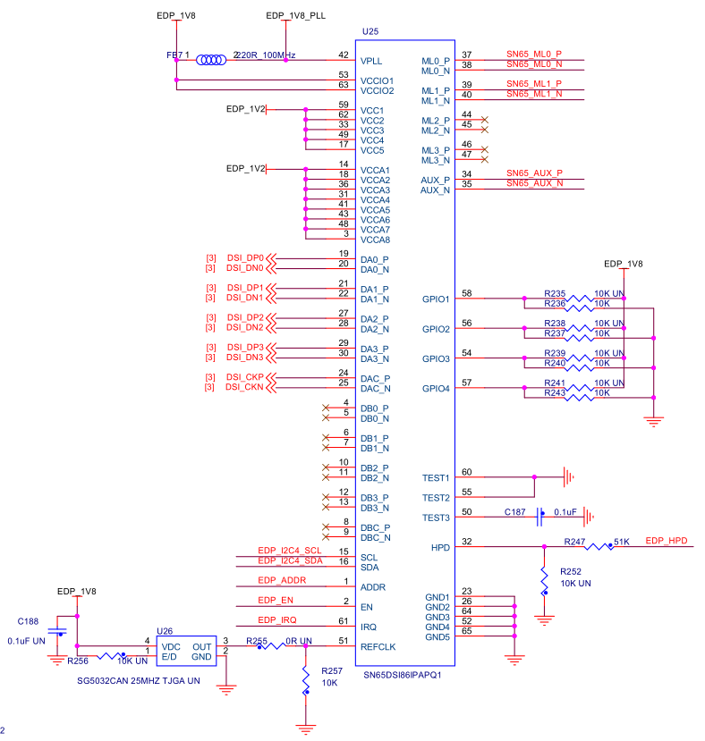
注:硬件修改REFCLK上需要贴上27M的晶振,TEST2引脚需要通过4.7K电阻上拉到1.8V.
3软件实现
3.1软件介绍
内核版本:Linux5.10;
SN65DSI86驱动:drivers/gpu/drm/bridge/ti-sn65dsi86.c
Panel驱动:drivers/gpu/drm/panel/panel-simple.c
3.2驱动移植
内核配置,需要打开如下两项
- CONFIG_DRM_TI_SN65DSI86=y
- CONFIG_DRM_PANEL_SIMPLE=y
1)设备树配置
- / {
- osc_27m: clock-osc-27m {
- compatible = "fixed-clock";
- #clock-cells = <0>;
- clock-frequency = <27000000>;
- clock-output-names = "osc_27m";
- };
-
- lcd_backlight: lcd_backlight {
- compatible = "pwm-backlight";
- pwms = <&pwm1 0 100000>;
- status = "okay";
-
- brightness-levels = < 0 1 2 3 4 5 6 7 8 9
- 10 11 12 13 14 15 16 17 18 19
- 20 21 22 23 24 25 26 27 28 29
- 30 31 32 33 34 35 36 37 38 39
- 40 41 42 43 44 45 46 47 48 49
- 50 51 52 53 54 55 56 57 58 59
- 60 61 62 63 64 65 66 67 68 69
- 70 71 72 73 74 75 76 77 78 79
- 80 81 82 83 84 85 86 87 88 89
- 90 91 92 93 94 95 96 97 98 99
- 100>;
- enable-gpios = <&gpio1 1 GPIO_ACTIVE_HIGH>;
- default-brightness-level = <80>;
- };
- panel {
- compatible = "test,test-edp-1080p"; //设置自己的屏幕匹配参数组
- backlight = <&lcd_backlight>;
- no-hpd;
-
- port {
- panel1_in: endpoint {
- remote-endpoint = <&sn65_out>;
- };
- };
- };
- };
- &pwm1 {
- pinctrl-names = "default";
- pinctrl-0 = <&pinctrl_pwm1>;
- status = "okay";
- };
-
- &i2c4 {
- clock-frequency = <400000>;
- pinctrl-names = "default";
- pinctrl-0 = <&pinctrl_i2c4>;
- status = "okay";
- sn65dsi86@2d {
- …….
- clock-names = "refclk"; //默认名字
- //SN65DSI86仅支持12 MHz, 19.2 MHz, 26 MHz, 27 MHz or 38.4 MHz.
- clocks = <&osc_27m>;
-
- ……
- port@1 {
- reg = <1>;
- sn65_out: endpoint {
- //data-lanes = <0 1 2 3>;
- //根据eDP屏的通道数设置,这里为2通道
- data-lanes = <0 1>;
- ……

2)驱动修改
添加显示屏的显示参数到驱动中,修改drivers/gpu/drm/panel/panel-simple.c:
- tatic const struct display_timing test_edp_1080p_timing = {
- .pixelclock = { 153000000, 153000000, 153000000 },
- .hactive = { 1920, 1920, 1920 },
- .hfront_porch = { 100, 100, 100 },
- …..
- .bus_format = MEDIA_BUS_FMT_RGB666_1X18,
- .connector_type = DRM_MODE_CONNECTOR_eDP,
- };
- static const struct of_device_id platform_of_match[] = {
- {
- .compatible = "test,test-edp-1080p",
- .data = &test_edp_1080p,
- },
修改sn65dsi86驱动以适应我们的板卡,修改drivers/gpu/drm/bridge/ti-sn65dsi86.c,修改DSI正确的模式,防止找不到注册的panel出现报错“couldnotfindanypanelnode”,开机过程中打印1次是正常的,SN65DSI86的驱动找不到Panel会被多次调用,直到找到panel为止。
- static int ti_sn_bridge_attach(struct drm_bridge *bridge,
- enum drm_bridge_attach_flags flags)
- {
- ...
- //dsi->mode_flags = MIPI_DSI_MODE_VIDEO;
- dsi->mode_flags = MIPI_DSI_MODE_VIDEO | MIPI_DSI_MODE_VIDEO_SYNC_PULSE |
- MIPI_DSI_MODE_EOT_PACKET | MIPI_DSI_MODE_VIDEO_HSE;
3)调试报错
在调试过程中碰到“Linktrainingfailed,linkisoff”的报错,是因为SN65DSI86默认只支持ASSR模式的eDP屏幕,对于不支持ASSR模式的eDP屏,硬件上则需要将TEST2引脚拉高到1.8V,且修改相关寄存器将芯片从ASSR模式变为支持标准的DP模式,修改如下:
- #define SN_ENH_FRAME_REG 0x5A
- #define ASSR_CONTROL BIT(0)
- ...
-
- static int ti_sn_link_training(struct ti_sn_bridge *pdata, int dp_rate_idx,
- const char **last_err_str)
- {
- unsigned int val;
- int ret;
- int i;
-
- /* set dp clk frequency value */
- regmap_update_bits(pdata->regmap, SN_DATARATE_CONFIG_REG,
- DP_DATARATE_MASK, DP_DATARATE(dp_rate_idx));
-
- regmap_write(pdata->regmap, 0xff, 0x07);
- regmap_write(pdata->regmap, 0x16, 0x01);
- regmap_write(pdata->regmap, 0xff, 0x00);
- /* For DisplayPort, use the standard DP scrambler seed. */
- regmap_update_bits(pdata->regmap, SN_ENH_FRAME_REG,ASSR_CONTROL, 0);
- /* enable DP PLL */
- regmap_write(pdata->regmap, SN_PLL_ENABLE_REG, 1);
- ...
如果未接eDP屏幕会出现如下报错:
- [ 2.299284] ti_sn65dsi86 3-002d: [drm:ti_sn_bridge_enable] ERROR Can't read lane count (-6); assuming 4
- [ 2.765851] ti_sn65dsi86 3-002d: [drm:ti_sn_bridge_enable] ERROR Can't read eDP rev (-6), assuming 1.1

