
- 1【SVR预测】差分进化改进灰狼算法优化SVR预测【含Matlab源码 1283期】_matlab svr
- 2js生成随机数(数字加字母)_js 随机数字字母
- 3C语言—指向函数的指针、全局变量和局部变量 、结构体、枚举_全局变量指针指向局部变量指针
- 4随机森林r语言实现(超详细)_随机森林 r语言实现
- 5Java排序算法(一)——归并排序_归并排序java
- 6判断链表是否有环,如果有返回环的入口,即链表有环证明,和找到环的入口证明(非常清晰的证明过程)_证明链表有环
- 7leetcode 接雨水二
- 8基于SpringSecurity 的登录详解(前后端分离)_springsecurity 前后端分离登录
- 9zabbix监控mysql自动发现_Zabbix自动发现并监控MySQL_MySQL
- 10北森云计算前端实习面试(技术总监三面)_云计算技术总监 面试问题
(硬件)SPI --- 串行外设设备接口_spi的scl是哪个脚
赞
踩
一.SPI介绍
SPI:串行外设设备接口(Serial Peripheral Interface),是一种高速的,全双工,同步的通信总线。
| 功能说明 | SPI总线 | IIC总线 |
| 通信方式 | 同步 串行 全双工 | 同步 串行 半双工 |
| 总线接口 | MOSI、MISO、SCL、CS | SDA、SCL |
| 拓扑结构 | 一主多从/一主一从 | 多主从 |
| 从机选择 | 片选引脚选择 | SDA上设备地址片选 |
| 通信速率 | 一般50MHz以下 | 100kMHz、400kMHz、3.4MHz |
| 数据格式 | 8位/16位 | 8位 |
| 传输顺序 | MSB/LSB | MSB |
SPI接口主要应用在存储芯片、AD转换器以及LCD中;
IIC采用电平协议,SPI采用边沿协议。
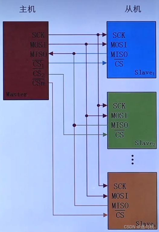
二.SPI结构框图介绍
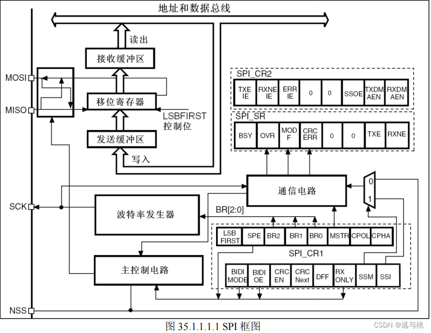
NSS一般用软件的,硬件的另有用处。
 数据发送:主机模式
帧格式:8bit/16bit;MSB在先/LSB在先;
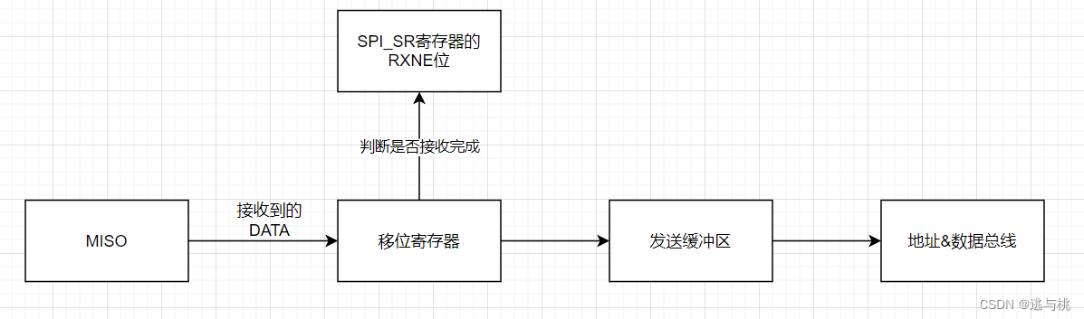 数据接收:主机模式。
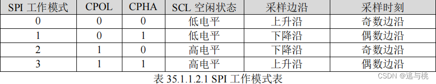
三.SPI工作模式介绍
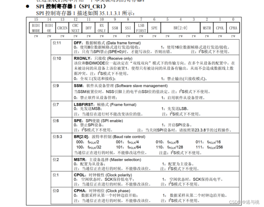
四.SPI相关寄存器介绍(F1/F4/F7)
| 寄存器 | 名称 | 作用 |
| SPI_CR1 | SPI控制寄存器1 | 用于配置SPI工作参数 |
| SPI_SR | SPI状态寄存器 | 用于查询当前SPI传输状态(TXE、RXNE) |
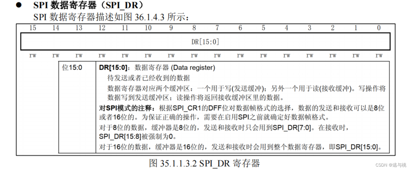
| SPI_DR | SPI数据寄存器 | 用于存放待发送数据或接收数据,有两个缓冲区(TX/RX) |
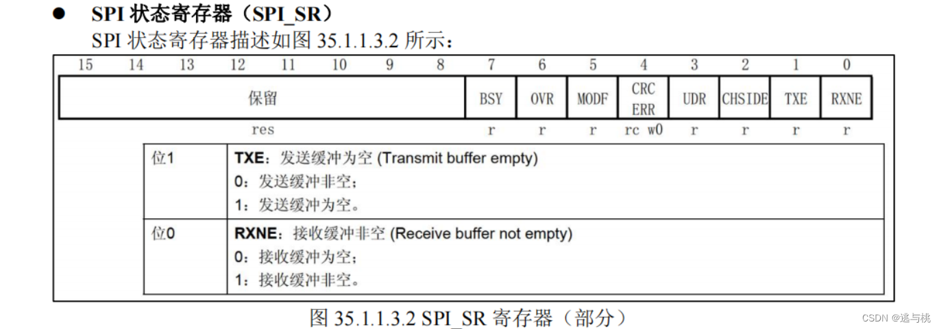 当TXE位置为1时,表示数据已经全部发送出去;
当RXNE位置为1时,表示已经接收到数据。
五.SPI相关HAL库驱动介绍
| 驱动函数 | 关联寄存器 | 功能描述 |
| __HAL_RCC_SPIx_CLK_ENABLE() | RCC_APB2ENR | 使能SPIx时钟 |
| HAL_SPI_Init() | SPI_CR1 | 初始化SPI |
| HAL_SPI_MspInit() | 初始化回调 | 初始化SPI相关引脚 |
| HAL_SPI_Transmit() | SPI_DR/SPI_SR | SPI发送 |
| HAL_SPI_Receive() | SPI_DR/SPI_SR | SPI接收 |
| HAL_SPI_TransmitReceive() | SPI_DR/SPI_SR | SPI接收发送 |
| __HAL_SPI_ENABLE() | SPI_CR1(SPE) | 使能SPI外设 |
| __HAL_SPI_DISABLE() | SPI_CR1(SPE) | 失能SPI外设 |
对于H7来说,还需要HAL_RCCEx_PeriphCLKConfig函数设置时钟源

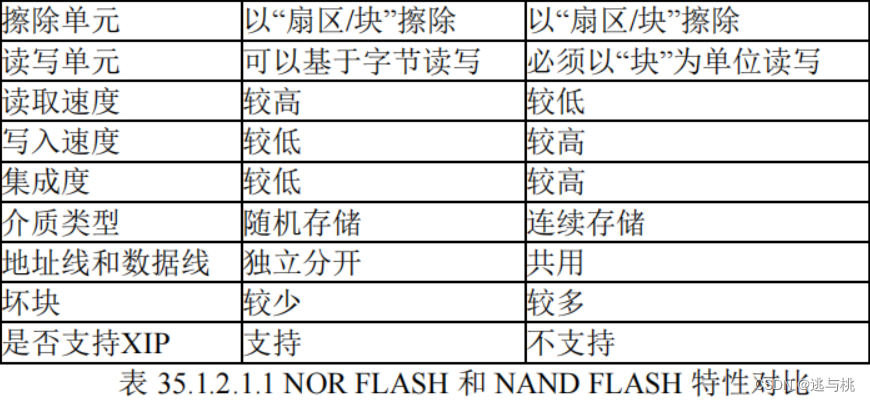
六.NOR FLASH介绍
<1>NOR FLASH介绍
FLASH 是常见的用于存储数据的半导体器件,它具有容量大、可重复擦写、按“扇区/块”擦除、掉电后数据可继续保存的特性。
常见的 FLASH 主要有 NOR FLASH 和 NAND FLASH 两种类型,NOR 和 NAND 是两种数字门电路,可以简单地认为FLASH 内部存储单元使用哪种门作存储单元就是哪类型的 FLASH。
FLASH物理特性:只能写0,不能写1,写1靠擦除。

<2>NM25Q128简介
NM25Q128,串行闪存器件,属于NOR FLASH中的一种,容量为128Mb(16MByte)。擦写周期可达10W次,可以将数据保存达20年之久。
- SPI数据传输时序:支持模式0(CPOL = 0,CPHA = 0)和模式3(CPOL = 1,CPHA = 1);
- 数据格式:数据长度8位大小,先发高位,再发地位。(MSB);
- 传输速度:支持标准模式104M bit/s。

CS 即片选信号输入,低电平有效;
DO 是 MISO 引脚,在 CLK 管脚 的下降沿输出数据;
WP 是写保护管脚,高电平可读可写,低电平仅仅可读;
DI 是 MOSI 引脚,主机发送的数据、地址和命令从 SI 引脚输入到芯片内部,在 CLK 管脚的上升沿捕获捕获数据;
CLK 是串行时钟引脚,为输入输出提供时钟脉冲;
HOLD 是保持管脚,低电平有效。
<3>NM25Q128存储结构
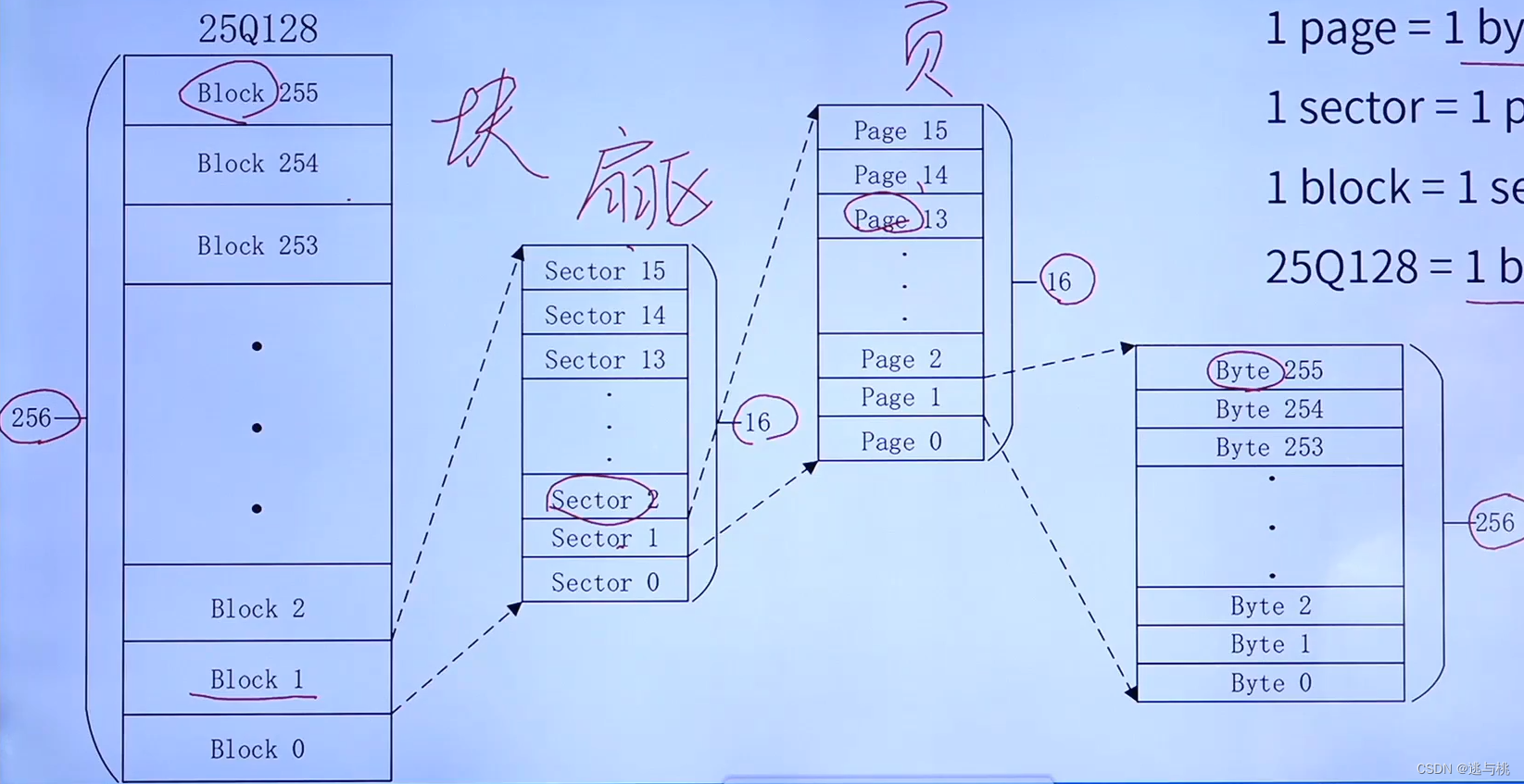
擦除可以是扇区、块、整个片;
写可以是页。
地址范围:0x0~0xFFFFFF
<4>NM25Q128常用指令
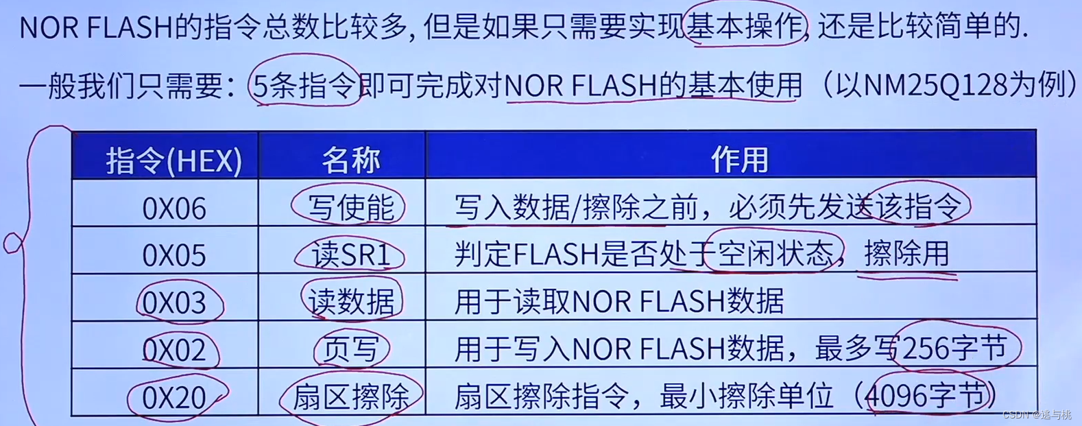
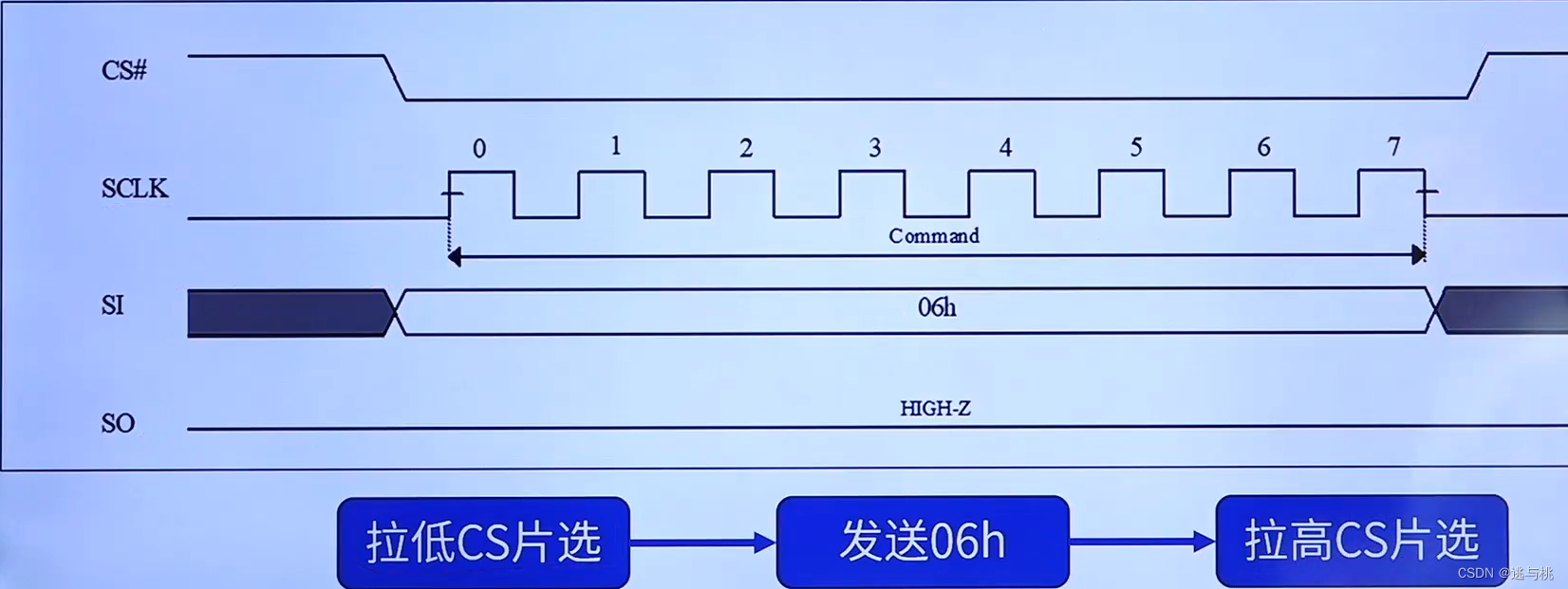
1.写使能 Write Enable(06H)
执行Page Program页写,Sector Erase扇区擦除,Block Erase块擦除,Chip Erase片擦除,Write Status Register写状态寄存器等指令前,需要写使能。
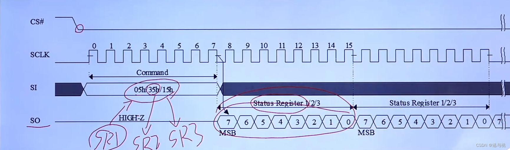
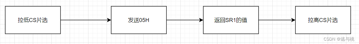
2.读状态寄存器Read Status Reg1(05H)
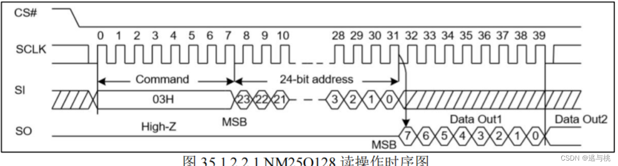
3.读时序 Read Data Bytes(03H)
 3.页写时序 PageProgram (02H)
页写命令最多可以向FLASH传输256个字节的数据。
4.扇区擦除时序 Sector Erase (20H)

FLASH存储器的特性决定了它只能把原来“1”的数据位改写为“0”,而原来为“0”的数据位不能直接改写为“1”。
写入数据前,检查内存空间情况是否满足,不满足需擦除。
<5>NM25Q128读/擦除/写 步骤
1.读操作步骤
- 发送读命令(03H):发送0x03读数据指令;
- 发送地址(24位):地址范围:0x0~0xFFFFFF,分3次发送;
- 读取数据:发送孔子姐(0xFF),读取数据,支持连续读。
2.擦除扇区步骤
- 发送写使能命令(06H):发送0x06,写使能命令;
- 等待空闲:等待NOR FLASH空闲;
- 发送擦除扇区命令(20H):发送擦除扇区命令(0x20);
- 发送地址(24位):发送要擦除的字节地址,自动擦除该地址所在扇区;
- 等待空闲:等待擦除完成(等待空闲状态)。
3.写操作步骤(极简)
- 擦除扇区(20H):通过前面的擦除步骤实现;
- 发送写使能命令(06H):发送0x06,写使能命令;
- 发送页写命令(02H):发送页写命令后,一次最多写入256字节;
- 发送地址(24位):发送要写入的地址;
- 发送数据:发送要写入的数据,一次最多写入256字节;
- 等待空闲:等待写入完成(等待空闲状态)。
七.NOR FLASH基本驱动步骤
<一>SPI配置步骤
- SPI工作参数配置初始化:工作模式、时钟特性、时钟相位等 --- HAL_SPI_Init;
- 使能SPI时钟和初始化相关引脚:GPIO模式设为复用推挽输出模式 --- HAL_SPI_MspInit;
- 使能SPI:__HAL_SPI_ENABLE;
- SPI传输数据:HAL_SPI_Transmit发送数据,HAL_SPI_Receive接收数据,HAL_SPI_TransmitReceive进行发送和接收;
- 设置SPI传输速度(可选):操作SPI_CR1寄存器中的波特率控制位,设置之前要先失能SPI之后再使能。
<二>NM25Q128驱动步骤
- 初始化片选引脚与SPI接口:相关GPIO初始化、SPI初始化(模式、位数、分频。MSB等);
- NM25Q128读取:0x03指令+24位地址+读取数据;
- NM25Q128扇区擦除:0x06指令+等待空闲+0x20指令+24位地址+等待空闲;
- NM25Q128写入:擦除扇区(可选)+0x06指令+0x02指令+24位地址+写入数据+等待空闲。

八.代码
驱动NM25Q128实现读和写1字节数据。
spi.c
- #include "./BSP/SPI/spi.h"
-
- SPI_HandleTypeDef g_spi2_handler; /* SPI2句柄 */
-
- /**
- * @brief SPI初始化代码
- * @note 主机模式,8位数据,禁止硬件片选
- * @param 无
- * @retval 无
- */
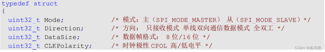
- void spi2_init(void)
- {
- SPI2_SPI_CLK_ENABLE(); /* SPI2时钟使能 */
-
- g_spi2_handler.Instance = SPI2_SPI; /* SPI2 */
- g_spi2_handler.Init.Mode = SPI_MODE_MASTER; /* 设置SPI工作模式,设置为主模式 */
- g_spi2_handler.Init.Direction = SPI_DIRECTION_2LINES; /* 设置SPI单向或者双向的数据模式:SPI设置为双线模式 */
- g_spi2_handler.Init.DataSize = SPI_DATASIZE_8BIT; /* 设置SPI的数据大小:SPI发送接收8位帧结构 */
- g_spi2_handler.Init.CLKPolarity = SPI_POLARITY_HIGH; /* 串行同步时钟的空闲状态为高电平 */
- g_spi2_handler.Init.CLKPhase = SPI_PHASE_2EDGE; /* 串行同步时钟的第二个跳变沿(上升或下降)数据被采样 */
- g_spi2_handler.Init.NSS = SPI_NSS_SOFT; /* NSS信号由硬件(NSS管脚)还是软件(使用SSI位)管理:内部NSS信号有SSI位控制 */
- g_spi2_handler.Init.BaudRatePrescaler = SPI_BAUDRATEPRESCALER_256; /* 定义波特率预分频的值:波特率预分频值为256 */
- g_spi2_handler.Init.FirstBit = SPI_FIRSTBIT_MSB; /* 指定数据传输从MSB位还是LSB位开始:数据传输从MSB位开始 */
- g_spi2_handler.Init.TIMode = SPI_TIMODE_DISABLE; /* 关闭TI模式 */
- g_spi2_handler.Init.CRCCalculation = SPI_CRCCALCULATION_DISABLE; /* 关闭硬件CRC校验 */
- g_spi2_handler.Init.CRCPolynomial = 7; /* CRC值计算的多项式 */
- HAL_SPI_Init(&g_spi2_handler); /* 初始化 */
-
- __HAL_SPI_ENABLE(&g_spi2_handler); /* 使能SPI2 */
-
- spi2_read_write_byte(0Xff); /* 启动传输, 实际上就是产生8个时钟脉冲, 达到清空DR的作用, 非必需 */
- }
-
- /**
- * @brief SPI底层驱动,时钟使能,引脚配置
- * @note 此函数会被HAL_SPI_Init()调用
- * @param hspi:SPI句柄
- * @retval 无
- */
- void HAL_SPI_MspInit(SPI_HandleTypeDef *hspi)
- {
- GPIO_InitTypeDef gpio_init_struct;
-
- if (hspi->Instance == SPI2_SPI)
- {
- SPI2_SCK_GPIO_CLK_ENABLE(); /* SPI2_SCK脚时钟使能 */
- SPI2_MISO_GPIO_CLK_ENABLE(); /* SPI2_MISO脚时钟使能 */
- SPI2_MOSI_GPIO_CLK_ENABLE(); /* SPI2_MOSI脚时钟使能 */
-
- /* SCK引脚模式设置(复用输出) */
- gpio_init_struct.Pin = SPI2_SCK_GPIO_PIN;
- gpio_init_struct.Mode = GPIO_MODE_AF_PP;
- gpio_init_struct.Pull = GPIO_PULLUP;
- gpio_init_struct.Speed = GPIO_SPEED_FREQ_HIGH;
- HAL_GPIO_Init(SPI2_SCK_GPIO_PORT, &gpio_init_struct);
-
- /* MISO引脚模式设置(复用输出) */
- gpio_init_struct.Pin = SPI2_MISO_GPIO_PIN;
- HAL_GPIO_Init(SPI2_MISO_GPIO_PORT, &gpio_init_struct);
-
- /* MOSI引脚模式设置(复用输出) */
- gpio_init_struct.Pin = SPI2_MOSI_GPIO_PIN;
- HAL_GPIO_Init(SPI2_MOSI_GPIO_PORT, &gpio_init_struct);
- }
- }
-
- /**
- * @brief SPI2速度设置函数
- * @note SPI2时钟选择来自APB1, 即PCLK1, 为36Mhz
- * SPI速度 = PCLK1 / 2^(speed + 1)
- * @param speed : SPI2时钟分频系数
- 取值为SPI_BAUDRATEPRESCALER_2~SPI_BAUDRATEPRESCALER_2 256
- * @retval 无
- */
- void spi2_set_speed(uint8_t speed)
- {
- assert_param(IS_SPI_BAUDRATE_PRESCALER(speed)); /* 判断有效性 */
- __HAL_SPI_DISABLE(&g_spi2_handler); /* 关闭SPI */
- g_spi2_handler.Instance->CR1 &= 0XFFC7; /* 位3-5清零,用来设置波特率 */
- g_spi2_handler.Instance->CR1 |= speed << 3; /* 设置SPI速度 */
- __HAL_SPI_ENABLE(&g_spi2_handler); /* 使能SPI */
- }
-
- /**
- * @brief SPI2读写一个字节数据
- * @param txdata : 要发送的数据(1字节)
- * @retval 接收到的数据(1字节)
- */
- uint8_t spi2_read_write_byte(uint8_t txdata)
- {
- uint8_t rxdata;
- HAL_SPI_TransmitReceive(&g_spi2_handler, &txdata, &rxdata, 1, 1000);
- return rxdata; /* 返回收到的数据 */
- }

spi.h
- #ifndef __SPI_H
- #define __SPI_H
-
- #include "./SYSTEM/sys/sys.h"
-
-
- /******************************************************************************************/
- /* SPI2 引脚 定义 */
-
- #define SPI2_SCK_GPIO_PORT GPIOB
- #define SPI2_SCK_GPIO_PIN GPIO_PIN_13
- #define SPI2_SCK_GPIO_CLK_ENABLE() do{ __HAL_RCC_GPIOB_CLK_ENABLE(); }while(0) /* PB口时钟使能 */
-
- #define SPI2_MISO_GPIO_PORT GPIOB
- #define SPI2_MISO_GPIO_PIN GPIO_PIN_14
- #define SPI2_MISO_GPIO_CLK_ENABLE() do{ __HAL_RCC_GPIOB_CLK_ENABLE(); }while(0) /* PB口时钟使能 */
-
- #define SPI2_MOSI_GPIO_PORT GPIOB
- #define SPI2_MOSI_GPIO_PIN GPIO_PIN_15
- #define SPI2_MOSI_GPIO_CLK_ENABLE() do{ __HAL_RCC_GPIOB_CLK_ENABLE(); }while(0) /* PB口时钟使能 */
-
- /* SPI2相关定义 */
- #define SPI2_SPI SPI2
- #define SPI2_SPI_CLK_ENABLE() do{ __HAL_RCC_SPI2_CLK_ENABLE(); }while(0) /* SPI2时钟使能 */
-
- /******************************************************************************************/
-
-
- /* SPI总线速度设置 */
- #define SPI_SPEED_2 0
- #define SPI_SPEED_4 1
- #define SPI_SPEED_8 2
- #define SPI_SPEED_16 3
- #define SPI_SPEED_32 4
- #define SPI_SPEED_64 5
- #define SPI_SPEED_128 6
- #define SPI_SPEED_256 7
-
-
- void spi2_init(void);
- void spi2_set_speed(uint8_t speed);
- uint8_t spi2_read_write_byte(uint8_t txdata);
-
- #endif
-
norflash.c
- #include "./BSP/SPI/spi.h"
- #include "./SYSTEM/delay/delay.h"
- #include "./SYSTEM/usart/usart.h"
- #include "./BSP/NORFLASH/norflash.h"
-
-
- uint16_t g_norflash_type = NM25Q128; /* 默认是NM25Q128 */
-
- /**
- * @brief 初始化SPI NOR FLASH
- * @param 无
- * @retval 无
- */
- void norflash_init(void)
- {
- uint8_t temp;
-
- NORFLASH_CS_GPIO_CLK_ENABLE(); /* NORFLASH CS脚 时钟使能 */
-
- GPIO_InitTypeDef gpio_init_struct;
- gpio_init_struct.Pin = NORFLASH_CS_GPIO_PIN;
- gpio_init_struct.Mode = GPIO_MODE_OUTPUT_PP;
- gpio_init_struct.Pull = GPIO_PULLUP;
- gpio_init_struct.Speed = GPIO_SPEED_FREQ_HIGH;
- HAL_GPIO_Init(NORFLASH_CS_GPIO_PORT, &gpio_init_struct); /* CS引脚模式设置(复用输出) */
-
- NORFLASH_CS(1); /* 取消片选 */
-
- spi2_init(); /* 初始化SPI2 */
- spi2_set_speed(SPI_SPEED_2); /* SPI2 切换到高速状态 18Mhz */
-
- g_norflash_type = norflash_read_id(); /* 读取FLASH ID. */
-
- if (g_norflash_type == W25Q256) /* SPI FLASH为W25Q256, 必须使能4字节地址模式 */
- {
- temp = norflash_read_sr(3); /* 读取状态寄存器3,判断地址模式 */
-
- if ((temp & 0X01) == 0) /* 如果不是4字节地址模式,则进入4字节地址模式 */
- {
- norflash_write_enable(); /* 写使能 */
- temp |= 1 << 1; /* ADP=1, 上电4位地址模式 */
- norflash_write_sr(3, temp); /* 写SR3 */
-
- NORFLASH_CS(0);
- spi2_read_write_byte(FLASH_Enable4ByteAddr); /* 使能4字节地址指令 */
- NORFLASH_CS(1);
- }
- }
-
- //printf("ID:%x\r\n", g_norflash_type);
- }
-
- /**
- * @brief 等待空闲
- * @param 无
- * @retval 无
- */
- static void norflash_wait_busy(void)
- {
- while ((norflash_read_sr(1) & 0x01) == 0x01); /* 等待BUSY位清空 */
- }
-
- /**
- * @brief 25QXX写使能
- * @note 将S1寄存器的WEL置位
- * @param 无
- * @retval 无
- */
- void norflash_write_enable(void)
- {
- NORFLASH_CS(0);
- spi2_read_write_byte(FLASH_WriteEnable); /* 发送写使能 */
- NORFLASH_CS(1);
- }
-
- /**
- * @brief 25QXX发送地址
- * @note 根据芯片型号的不同, 发送24ibt / 32bit地址
- * @param address : 要发送的地址
- * @retval 无
- */
- static void norflash_send_address(uint32_t address)
- {
- if (g_norflash_type == W25Q256) /* 只有W25Q256支持4字节地址模式 */
- {
- spi2_read_write_byte((uint8_t)((address)>>24)); /* 发送 bit31 ~ bit24 地址 */
- }
- spi2_read_write_byte((uint8_t)((address)>>16)); /* 发送 bit23 ~ bit16 地址 */
- spi2_read_write_byte((uint8_t)((address)>>8)); /* 发送 bit15 ~ bit8 地址 */
- spi2_read_write_byte((uint8_t)address); /* 发送 bit7 ~ bit0 地址 */
- }
-
- /**
- * @brief 读取25QXX的状态寄存器,25QXX一共有3个状态寄存器
- * @note 状态寄存器1:
- * BIT7 6 5 4 3 2 1 0
- * SPR RV TB BP2 BP1 BP0 WEL BUSY
- * SPR:默认0,状态寄存器保护位,配合WP使用
- * TB,BP2,BP1,BP0:FLASH区域写保护设置
- * WEL:写使能锁定
- * BUSY:忙标记位(1,忙;0,空闲)
- * 默认:0x00
- *
- * 状态寄存器2:
- * BIT7 6 5 4 3 2 1 0
- * SUS CMP LB3 LB2 LB1 (R) QE SRP1
- *
- * 状态寄存器3:
- * BIT7 6 5 4 3 2 1 0
- * HOLD/RST DRV1 DRV0 (R) (R) WPS ADP ADS
- *
- * @param regno: 状态寄存器号,范围:1~3
- * @retval 状态寄存器值
- */
- uint8_t norflash_read_sr(uint8_t regno)
- {
- uint8_t byte = 0, command = 0;
-
- switch (regno)
- {
- case 1:
- command = FLASH_ReadStatusReg1; /* 读状态寄存器1指令 */
- break;
-
- case 2:
- command = FLASH_ReadStatusReg2; /* 读状态寄存器2指令 */
- break;
-
- case 3:
- command = FLASH_ReadStatusReg3; /* 读状态寄存器3指令 */
- break;
-
- default:
- command = FLASH_ReadStatusReg1;
- break;
- }
-
- NORFLASH_CS(0);
- spi2_read_write_byte(command); /* 发送读寄存器命令 */
- byte = spi2_read_write_byte(0Xff); /* 读取一个字节 */
- NORFLASH_CS(1);
-
- return byte;
- }
-
- /**
- * @brief 写25QXX状态寄存器
- * @note 寄存器说明见norflash_read_sr函数说明
- * @param regno: 状态寄存器号,范围:1~3
- * @param sr : 要写入状态寄存器的值
- * @retval 无
- */
- void norflash_write_sr(uint8_t regno, uint8_t sr)
- {
- uint8_t command = 0;
-
- switch (regno)
- {
- case 1:
- command = FLASH_WriteStatusReg1; /* 写状态寄存器1指令 */
- break;
-
- case 2:
- command = FLASH_WriteStatusReg2; /* 写状态寄存器2指令 */
- break;
-
- case 3:
- command = FLASH_WriteStatusReg3; /* 写状态寄存器3指令 */
- break;
-
- default:
- command = FLASH_WriteStatusReg1;
- break;
- }
-
- NORFLASH_CS(0);
- spi2_read_write_byte(command); /* 发送读寄存器命令 */
- spi2_read_write_byte(sr); /* 写入一个字节 */
- NORFLASH_CS(1);
- }
-
- /**
- * @brief 读取芯片ID
- * @param 无
- * @retval FLASH芯片ID
- * @note 芯片ID列表见: norflash.h, 芯片列表部分
- */
- uint16_t norflash_read_id(void)
- {
- uint16_t deviceid;
-
- NORFLASH_CS(0);
- spi2_read_write_byte(FLASH_ManufactDeviceID); /* 发送读 ID 命令 */
- spi2_read_write_byte(0); /* 写入一个字节 */
- spi2_read_write_byte(0);
- spi2_read_write_byte(0);
- deviceid = spi2_read_write_byte(0xFF) << 8; /* 读取高8位字节 */
- deviceid |= spi2_read_write_byte(0xFF); /* 读取低8位字节 */
- NORFLASH_CS(1);
-
- return deviceid;
- }
-
- /**
- * @brief 读取SPI FLASH
- * @note 在指定地址开始读取指定长度的数据
- * @param pbuf : 数据存储区
- * @param addr : 开始读取的地址(最大32bit)
- * @param datalen : 要读取的字节数(最大65535)
- * @retval 无
- */
- void norflash_read(uint8_t *pbuf, uint32_t addr, uint16_t datalen)
- {
- uint16_t i;
-
- NORFLASH_CS(0);
- spi2_read_write_byte(FLASH_ReadData); /* 发送读取命令 */
- norflash_send_address(addr); /* 发送地址 */
-
- for(i=0;i<datalen;i++)
- {
- pbuf[i] = spi2_read_write_byte(0XFF); /* 循环读取 */
- }
-
- NORFLASH_CS(1);
- }
-
- /**
- * @brief SPI在一页(0~65535)内写入少于256个字节的数据
- * @note 在指定地址开始写入最大256字节的数据
- * @param pbuf : 数据存储区
- * @param addr : 开始写入的地址(最大32bit)
- * @param datalen : 要写入的字节数(最大256),该数不应该超过该页的剩余字节数!!!
- * @retval 无
- */
- static void norflash_write_page(uint8_t *pbuf, uint32_t addr, uint16_t datalen)
- {
- uint16_t i;
-
- norflash_write_enable(); /* 写使能 */
-
- NORFLASH_CS(0);
- spi2_read_write_byte(FLASH_PageProgram); /* 发送写页命令 */
- norflash_send_address(addr); /* 发送地址 */
-
- for(i=0;i<datalen;i++)
- {
- spi2_read_write_byte(pbuf[i]); /* 循环写入 */
- }
-
- NORFLASH_CS(1);
- norflash_wait_busy(); /* 等待写入结束 */
- }
-
- /**
- * @brief 无检验写SPI FLASH
- * @note 必须确保所写的地址范围内的数据全部为0XFF,否则在非0XFF处写入的数据将失败!
- * 具有自动换页功能
- * 在指定地址开始写入指定长度的数据,但是要确保地址不越界!
- *
- * @param pbuf : 数据存储区
- * @param addr : 开始写入的地址(最大32bit)
- * @param datalen : 要写入的字节数(最大65535)
- * @retval 无
- */
- static void norflash_write_nocheck(uint8_t *pbuf, uint32_t addr, uint16_t datalen)
- {
- uint16_t pageremain;
- pageremain = 256 - addr % 256; /* 单页剩余的字节数 */
-
- if (datalen <= pageremain) /* 不大于256个字节 */
- {
- pageremain = datalen;
- }
-
- while (1)
- {
- /* 当写入字节比页内剩余地址还少的时候, 一次性写完
- * 当写入直接比页内剩余地址还多的时候, 先写完整个页内剩余地址, 然后根据剩余长度进行不同处理
- */
- norflash_write_page(pbuf, addr, pageremain);
-
- if (datalen == pageremain) /* 写入结束了 */
- {
- break;
- }
- else /* datalen > pageremain */
- {
- pbuf += pageremain; /* pbuf指针地址偏移,前面已经写了pageremain字节 */
- addr += pageremain; /* 写地址偏移,前面已经写了pageremain字节 */
- datalen -= pageremain; /* 写入总长度减去已经写入了的字节数 */
-
- if (datalen > 256) /* 剩余数据还大于一页,可以一次写一页 */
- {
- pageremain = 256; /* 一次可以写入256个字节 */
- }
- else /* 剩余数据小于一页,可以一次写完 */
- {
- pageremain = datalen; /* 不够256个字节了 */
- }
- }
- }
- }
-
- /**
- * @brief 写SPI FLASH
- * @note 在指定地址开始写入指定长度的数据 , 该函数带擦除操作!
- * SPI FLASH 一般是: 256个字节为一个Page, 4Kbytes为一个Sector, 16个扇区为1个Block
- * 擦除的最小单位为Sector.
- *
- * @param pbuf : 数据存储区
- * @param addr : 开始写入的地址(最大32bit)
- * @param datalen : 要写入的字节数(最大65535)
- * @retval 无
- */
- uint8_t g_norflash_buf[4096]; /* 扇区缓存 */
-
- void norflash_write(uint8_t *pbuf, uint32_t addr, uint16_t datalen)
- {
- uint32_t secpos;
- uint16_t secoff;
- uint16_t secremain;
- uint16_t i;
- uint8_t *norflash_buf;
-
- norflash_buf = g_norflash_buf;
- secpos = addr / 4096; /* 扇区地址 */
- secoff = addr % 4096; /* 在扇区内的偏移 */
- secremain = 4096 - secoff; /* 扇区剩余空间大小 */
-
- //printf("ad:%X,nb:%X\r\n", addr, datalen); /* 测试用 */
- if (datalen <= secremain)
- {
- secremain = datalen; /* 不大于4096个字节 */
- }
-
- while (1)
- {
- norflash_read(norflash_buf, secpos * 4096, 4096); /* 读出整个扇区的内容 */
-
- for (i = 0; i < secremain; i++) /* 校验数据 */
- {
- if (norflash_buf[secoff + i] != 0XFF)
- {
- break; /* 需要擦除, 直接退出for循环 */
- }
- }
-
- if (i < secremain) /* 需要擦除 */
- {
- norflash_erase_sector(secpos); /* 擦除这个扇区 */
-
- for (i = 0; i < secremain; i++) /* 复制 */
- {
- norflash_buf[i + secoff] = pbuf[i];
- }
-
- norflash_write_nocheck(norflash_buf, secpos * 4096, 4096); /* 写入整个扇区 */
- }
- else /* 写已经擦除了的,直接写入扇区剩余区间. */
- {
- norflash_write_nocheck(pbuf, addr, secremain); /* 直接写扇区 */
- }
-
- if (datalen == secremain)
- {
- break; /* 写入结束了 */
- }
- else /* 写入未结束 */
- {
- secpos++; /* 扇区地址增1 */
- secoff = 0; /* 偏移位置为0 */
-
- pbuf += secremain; /* 指针偏移 */
- addr += secremain; /* 写地址偏移 */
- datalen -= secremain; /* 字节数递减 */
-
- if (datalen > 4096)
- {
- secremain = 4096; /* 下一个扇区还是写不完 */
- }
- else
- {
- secremain = datalen;/* 下一个扇区可以写完了 */
- }
- }
- }
- }
-
- /**
- * @brief 擦除整个芯片
- * @note 等待时间超长...
- * @param 无
- * @retval 无
- */
- void norflash_erase_chip(void)
- {
- norflash_write_enable(); /* 写使能 */
- norflash_wait_busy(); /* 等待空闲 */
- NORFLASH_CS(0);
- spi2_read_write_byte(FLASH_ChipErase); /* 发送读寄存器命令 */
- NORFLASH_CS(1);
- norflash_wait_busy(); /* 等待芯片擦除结束 */
- }
-
- /**
- * @brief 擦除一个扇区
- * @note 注意,这里是扇区地址,不是字节地址!!
- * 擦除一个扇区的最少时间:150ms
- *
- * @param saddr : 扇区地址 根据实际容量设置
- * @retval 无
- */
- void norflash_erase_sector(uint32_t saddr)
- {
- //printf("fe:%x\r\n", saddr); /* 监视falsh擦除情况,测试用 */
- saddr *= 4096;
- norflash_write_enable(); /* 写使能 */
- norflash_wait_busy(); /* 等待空闲 */
-
- NORFLASH_CS(0);
- spi2_read_write_byte(FLASH_SectorErase); /* 发送写页命令 */
- norflash_send_address(saddr); /* 发送地址 */
- NORFLASH_CS(1);
- norflash_wait_busy(); /* 等待扇区擦除完成 */
- }
-
norflash.h
- #ifndef __norflash_H
- #define __norflash_H
-
- #include "./SYSTEM/sys/sys.h"
-
-
- /******************************************************************************************/
- /* NORFLASH 片选 引脚 定义 */
-
- #define NORFLASH_CS_GPIO_PORT GPIOB
- #define NORFLASH_CS_GPIO_PIN GPIO_PIN_12
- #define NORFLASH_CS_GPIO_CLK_ENABLE() do{ __HAL_RCC_GPIOB_CLK_ENABLE(); }while(0) /* PB口时钟使能 */
-
- /******************************************************************************************/
-
- /* NORFLASH 片选信号 */
- #define NORFLASH_CS(x) do{ x ? \
- HAL_GPIO_WritePin(NORFLASH_CS_GPIO_PORT, NORFLASH_CS_GPIO_PIN, GPIO_PIN_SET) : \
- HAL_GPIO_WritePin(NORFLASH_CS_GPIO_PORT, NORFLASH_CS_GPIO_PIN, GPIO_PIN_RESET); \
- }while(0)
-
- /* FLASH芯片列表 */
- #define W25Q80 0XEF13 /* W25Q80 芯片ID */
- #define W25Q16 0XEF14 /* W25Q16 芯片ID */
- #define W25Q32 0XEF15 /* W25Q32 芯片ID */
- #define W25Q64 0XEF16 /* W25Q64 芯片ID */
- #define W25Q128 0XEF17 /* W25Q128 芯片ID */
- #define W25Q256 0XEF18 /* W25Q256 芯片ID */
- #define BY25Q64 0X6816 /* BY25Q64 芯片ID */
- #define BY25Q128 0X6817 /* BY25Q128 芯片ID */
- #define NM25Q64 0X5216 /* NM25Q64 芯片ID */
- #define NM25Q128 0X5217 /* NM25Q128 芯片ID */
-
- extern uint16_t norflash_TYPE; /* 定义FLASH芯片型号 */
-
- /* 指令表 */
- #define FLASH_WriteEnable 0x06
- #define FLASH_WriteDisable 0x04
- #define FLASH_ReadStatusReg1 0x05
- #define FLASH_ReadStatusReg2 0x35
- #define FLASH_ReadStatusReg3 0x15
- #define FLASH_WriteStatusReg1 0x01
- #define FLASH_WriteStatusReg2 0x31
- #define FLASH_WriteStatusReg3 0x11
- #define FLASH_ReadData 0x03
- #define FLASH_FastReadData 0x0B
- #define FLASH_FastReadDual 0x3B
- #define FLASH_FastReadQuad 0xEB
- #define FLASH_PageProgram 0x02
- #define FLASH_PageProgramQuad 0x32
- #define FLASH_BlockErase 0xD8
- #define FLASH_SectorErase 0x20
- #define FLASH_ChipErase 0xC7
- #define FLASH_PowerDown 0xB9
- #define FLASH_ReleasePowerDown 0xAB
- #define FLASH_DeviceID 0xAB
- #define FLASH_ManufactDeviceID 0x90
- #define FLASH_JedecDeviceID 0x9F
- #define FLASH_Enable4ByteAddr 0xB7
- #define FLASH_Exit4ByteAddr 0xE9
- #define FLASH_SetReadParam 0xC0
- #define FLASH_EnterQPIMode 0x38
- #define FLASH_ExitQPIMode 0xFF
-
- /* 静态函数 */
- static void norflash_wait_busy(void); /* 等待空闲 */
- static void norflash_send_address(uint32_t address);/* 发送地址 */
- static void norflash_write_page(uint8_t *pbuf, uint32_t addr, uint16_t datalen); /* 写入page */
- static void norflash_write_nocheck(uint8_t *pbuf, uint32_t addr, uint16_t datalen); /* 写flash,不带擦除 */
-
- /* 普通函数 */
- void norflash_init(void); /* 初始化25QXX */
- uint16_t norflash_read_id(void); /* 读取FLASH ID */
- void norflash_write_enable(void); /* 写使能 */
- uint8_t norflash_read_sr(uint8_t regno); /* 读取状态寄存器 */
- void norflash_write_sr(uint8_t regno,uint8_t sr); /* 写状态寄存器 */
-
- void norflash_erase_chip(void); /* 整片擦除 */
- void norflash_erase_sector(uint32_t saddr); /* 扇区擦除 */
- void norflash_read(uint8_t *pbuf, uint32_t addr, uint16_t datalen); /* 读取flash */
- void norflash_write(uint8_t *pbuf, uint32_t addr, uint16_t datalen); /* 写入flash */
-
- #endif
-
main.c
- #include "./SYSTEM/sys/sys.h"
- #include "./SYSTEM/usart/usart.h"
- #include "./SYSTEM/delay/delay.h"
- #include "./USMART/usmart.h"
- #include "./BSP/LED/led.h"
- #include "./BSP/LCD/lcd.h"
- #include "./BSP/KEY/key.h"
- #include "./BSP/NORFLASH/norflash.h"
-
- /* 要写入到FLASH的字符串数组 */
- const uint8_t g_text_buf[] = {"STM32 SPI TEST"};
-
- #define TEXT_SIZE sizeof(g_text_buf) /* TEXT字符串长度 */
-
- int main(void)
- {
- uint8_t key;
- uint16_t i = 0;
- uint8_t datatemp[TEXT_SIZE];
- uint32_t flashsize;
- uint16_t id = 0;
-
- HAL_Init(); /* 初始化HAL库 */
- sys_stm32_clock_init(RCC_PLL_MUL9); /* 设置时钟, 72Mhz */
- delay_init(72); /* 延时初始化 */
- usart_init(115200); /* 串口初始化为115200 */
- usmart_dev.init(72); /* 初始化USMART */
- led_init(); /* 初始化LED */
- lcd_init(); /* 初始化LCD */
- key_init(); /* 初始化按键 */
- norflash_init(); /* 初始化NORFLASH */
-
- lcd_show_string(30, 50, 200, 16, 16, "STM32", RED);
- lcd_show_string(30, 70, 200, 16, 16, "SPI TEST", RED);
- lcd_show_string(30, 90, 200, 16, 16, "ATOM@ALIENTEK", RED);
- lcd_show_string(30, 110, 200, 16, 16, "KEY1:Write KEY0:Read", RED); /* 显示提示信息 */
-
- id = norflash_read_id(); /* 读取FLASH ID */
-
- while ((id == 0) || (id == 0XFFFF)) /* 检测不到FLASH芯片 */
- {
- lcd_show_string(30, 130, 200, 16, 16, "FLASH Check Failed!", RED);
- delay_ms(500);
- lcd_show_string(30, 130, 200, 16, 16, "Please Check! ", RED);
- delay_ms(500);
- LED0_TOGGLE(); /* LED0闪烁 */
- }
-
- lcd_show_string(30, 130, 200, 16, 16, "SPI FLASH Ready!", BLUE);
- flashsize = 16 * 1024 * 1024; /* FLASH 大小为16M字节 */
-
- while (1)
- {
- key = key_scan(0);
-
- if (key == KEY1_PRES) /* KEY1按下,写入 */
- {
- lcd_fill(0, 150, 239, 319, WHITE); /* 清除半屏 */
- lcd_show_string(30, 150, 200, 16, 16, "Start Write FLASH....", BLUE);
- sprintf((char *)datatemp, "%s%d", (char *)g_text_buf, i);
- norflash_write((uint8_t *)datatemp, flashsize - 100, TEXT_SIZE); /* 从倒数第100个地址处开始,写入SIZE长度的数据 */
- lcd_show_string(30, 150, 200, 16, 16, "FLASH Write Finished!", BLUE); /* 提示传送完成 */
- }
-
- if (key == KEY0_PRES) /* KEY0按下,读取字符串并显示 */
- {
- lcd_show_string(30, 150, 200, 16, 16, "Start Read FLASH... . ", BLUE);
- norflash_read(datatemp, flashsize - 100, TEXT_SIZE); /* 从倒数第100个地址处开始,读出SIZE个字节 */
- lcd_show_string(30, 150, 200, 16, 16, "The Data Readed Is: ", BLUE); /* 提示传送完成 */
- lcd_show_string(30, 170, 200, 16, 16, (char *)datatemp, BLUE); /* 显示读到的字符串 */
- }
-
- i++;
-
- if (i == 20)
- {
- LED0_TOGGLE(); /* LED0闪烁 */
- i = 0;
- }
-
- delay_ms(10);
- }
- }

