
热门标签
热门文章
- 1PSD 格式文件除了 PS ,还能用什么软件打开?_psd文件只有ps能打开吗
- 2如何在Linux上搭建本地Docker Registry镜像仓库并实现公网访问
- 3Linux OpenEuler(欧拉系统)无公网ip实现SSH远程连接_欧拉系统添加ssh用户
- 4Postman中参数填写方式_postman路径参数怎么填
- 5工作方法 - 戒定慧_工作中戒定慧行动
- 6向量点乘(即内积)和叉乘(即外积、向量积)区别与意义分析
- 72023 英特尔On技术创新大会直播 | AI 融合发展之旅
- 8<Linux开发>驱动开发 -之-内核定时器与中断_linux 定时器中断
- 9实践tcpdump命令,成为网络数据抓包高手_tcpdump -nps
- 10国内外人工智能AI工具网站大全(一键收藏,应有尽有)_国内ai网站
当前位置: article > 正文
STM32 HAL库 SPI主从机通信_stm32 16位数据 spi 主从机通信
作者:prog456 | 2024-01-31 14:24:32
赞
踩
stm32 16位数据 spi 主从机通信
STM32 HAL库 SPI主从机通信
1.简介
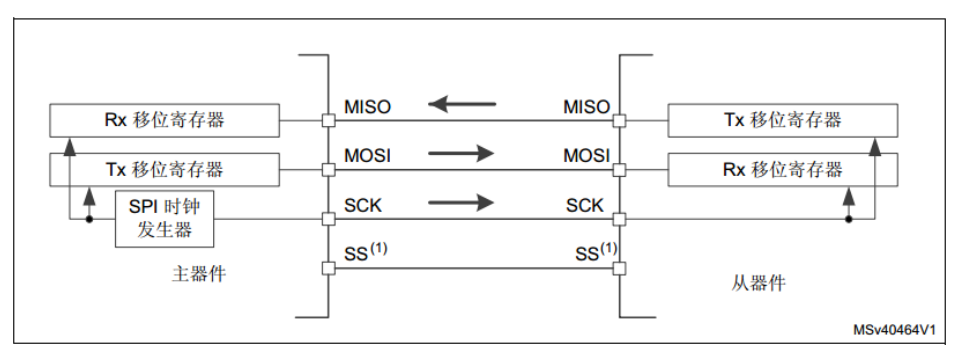
SPI可以实现全双工通信,分为主器件和从器件,主器件发起时钟控制通信的开始和结束,从器件只能被动等待住器件发起通信。如果主器件一直不发起通信,没有时钟产生,从器件是没办法发送数据的,只有主器件产生了时钟之后从器件才能将寄存器中的数据移位发送出来。
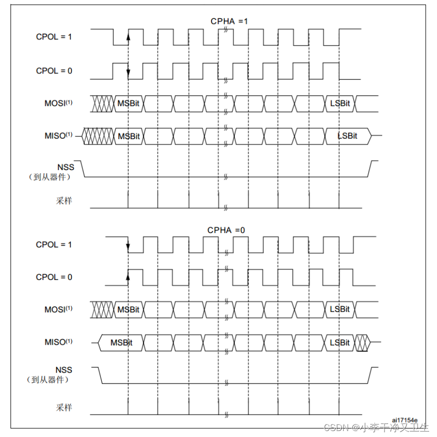
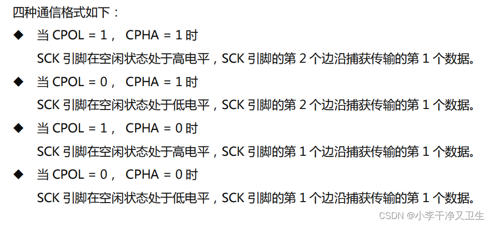
SPI有4中通信格式,
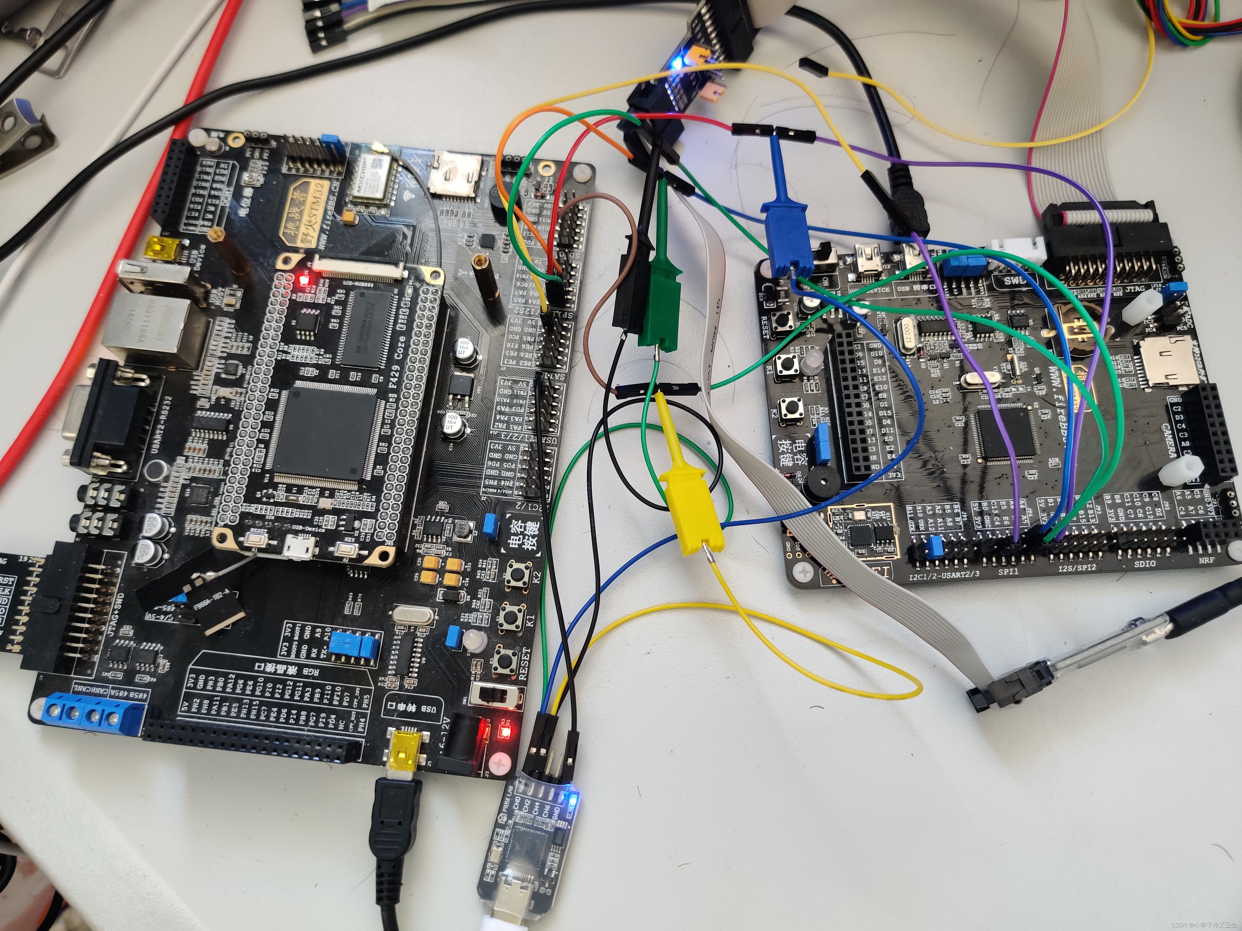
实验采用的平台为STM32F429为主机,STM32F103为从机进行数据通信。
2.工程
整体的通信思路是主机首先给从机发送一个字节的通信开始命令,从机接收到命令之后回复一个字节的确认信号,然后主句发送32字节的数据,从机接收到数据之后再通过SPI发送回主机,主机接收到数据之后通过串口发送,以此检验SPI的发送和接收是否正确。
2.1主机工程
![[外链图片转存失败,源站可能有防盗链机制,建议将图片保存下来直接上传(img-yCSukDmL-1660010618842)(https://raw.githubusercontent.com/Master-4869/pictures/main/image-20220809085927005.png)]](https://img-blog.csdnimg.cn/97f8efc1aea04ceeb1c1fde4f225754e.png)
在cubeMX中配置SPI时,CPHA不是0和1,反而是1和2,这里1对应的就是CPHA=0,在第一个时钟边沿捕获数据。
/* USER CODE BEGIN Header */
/**
  ******************************************************************************
  * @file           : main.c
  * @brief          : Main program body
  ******************************************************************************
  * @attention
  *
  * Copyright (c) 2022 STMicroelectronics.
  * All rights reserved.
  *
  * This software is licensed under terms that can be found in the LICENSE file
  * in the root directory of this software component.
  * If no LICENSE file comes with this software, it is provided AS-IS.
  *
  ******************************************************************************
  */
/* USER CODE END Header */
/* Includes ------------------------------------------------------------------*/
#include "main.h"
#include "dma.h"
#include "rng.h"
#include "spi.h"
#include "usart.h"
#include "gpio.h"

/* Private includes ----------------------------------------------------------*/
/* USER CODE BEGIN Includes */

/* USER CODE END Includes */

/* Private typedef -----------------------------------------------------------*/
/* USER CODE BEGIN PTD */
uint32_t random[32] = {0};
uint8_t random_8[32] = {1,2,3,4,5,6,7,8,9,10,11,12,13,14,15,16,17,18,19,20,21,22,23,24,25,26,27,28,29,30,31,32};
	uint8_t random_8_1[8] = {0x05,0x0b,0x0b,0x0b,0x0b,0x0b,0x0b,0x0b};
uint8_t rece_data[32] = {0};
/* USER CODE END PTD */

/* Private define ------------------------------------------------------------*/
/* USER CODE BEGIN PD */
/* USER CODE END PD */

/* Private macro -------------------------------------------------------------*/
/* USER CODE BEGIN PM */

/* USER CODE END PM */

/* Private variables ---------------------------------------------------------*/

/* USER CODE BEGIN PV */
void Delay_us(__IO uint32_t delay);
/* USER CODE END PV */

/* Private function prototypes -----------------------------------------------*/
void SystemClock_Config(void);
/* USER CODE BEGIN PFP */

/* USER CODE END PFP */

/* Private user code ---------------------------------------------------------*/
/* USER CODE BEGIN 0 */
uint8_t cmd_buffer = 0;
/* USER CODE END 0 */

/**
  * @brief  The application entry point.
  * @retval int
  */
int main(void)
{
  /* USER CODE BEGIN 1 */
  uint8_t test = 0x05;
	uint8_t test_1 = 0x07;

  /* USER CODE END 1 */

  /* MCU Configuration--------------------------------------------------------*/

  /* Reset of all peripherals, Initializes the Flash interface and the Systick. */
  HAL_Init();

  /* USER CODE BEGIN Init */

  /* USER CODE END Init */

  /* Configure the system clock */
  SystemClock_Config();

  /* USER CODE BEGIN SysInit */

  /* USER CODE END SysInit */

  /* Initialize all configured peripherals */
  MX_GPIO_Init();
  MX_DMA_Init();
  MX_SPI1_Init();
  MX_USART1_UART_Init();
  MX_RNG_Init();
  /* USER CODE BEGIN 2 */
			for(int i = 0; i<32;i++)
		{
			HAL_RNG_GenerateRandomNumber(&hrng,&random[i]);
			//random_8[i] = (uint8_t)random[i];
		}
  /* USER CODE END 2 */

  /* Infinite loop */
  /* USER CODE BEGIN WHILE */
  while (1)
  {
		HAL_GPIO_WritePin(GPIOA, GPIO_PIN_4, GPIO_PIN_SET);
		Delay_us(2);
		HAL_SPI_Transmit(&hspi1,&test,1,10);
		HAL_GPIO_WritePin(GPIOA, GPIO_PIN_4, GPIO_PIN_RESET);
		HAL_Delay(1);
		HAL_GPIO_WritePin(GPIOA, GPIO_PIN_4, GPIO_PIN_SET);

		HAL_SPI_Receive(&hspi1,&cmd_buffer,1,10);
		HAL_GPIO_WritePin(GPIOA, GPIO_PIN_4, GPIO_PIN_RESET);

		if(cmd_buffer == 0x06)
		{
			cmd_buffer = 0;
			HAL_Delay(2);

			HAL_GPIO_WritePin(GPIOA, GPIO_PIN_4, GPIO_PIN_SET);
			Delay_us(20);
			HAL_SPI_Transmit(&hspi1,random_8,32,10);
			HAL_GPIO_WritePin(GPIOA, GPIO_PIN_4, GPIO_PIN_RESET);

		HAL_Delay(1);
			HAL_GPIO_WritePin(GPIOA, GPIO_PIN_4, GPIO_PIN_SET);
			Delay_us(20);
			//HAL_Delay(1);
		HAL_SPI_Receive(&hspi1,rece_data,32,10);
			HAL_GPIO_WritePin(GPIOA, GPIO_PIN_4, GPIO_PIN_RESET);
		}
		HAL_UART_Transmit(&huart1,rece_data,32,10);
		for(int i = 0;i < 32;i++)
		{
			rece_data[i] = 0;
		}
		HAL_Delay(100);
    /* USER CODE END WHILE */

    /* USER CODE BEGIN 3 */
  }
  /* USER CODE END 3 */
}

/**
  * @brief System Clock Configuration
  * @retval None
  */
void SystemClock_Config(void)
{
  RCC_OscInitTypeDef RCC_OscInitStruct = {0};
  RCC_ClkInitTypeDef RCC_ClkInitStruct = {0};

  /** Configure the main internal regulator output voltage
  */
  __HAL_RCC_PWR_CLK_ENABLE();
  __HAL_PWR_VOLTAGESCALING_CONFIG(PWR_REGULATOR_VOLTAGE_SCALE1);

  /** Initializes the RCC Oscillators according to the specified parameters
  * in the RCC_OscInitTypeDef structure.
  */
  RCC_OscInitStruct.OscillatorType = RCC_OSCILLATORTYPE_HSE;
  RCC_OscInitStruct.HSEState = RCC_HSE_ON;
  RCC_OscInitStruct.PLL.PLLState = RCC_PLL_ON;
  RCC_OscInitStruct.PLL.PLLSource = RCC_PLLSOURCE_HSE;
  RCC_OscInitStruct.PLL.PLLM = 15;
  RCC_OscInitStruct.PLL.PLLN = 216;
  RCC_OscInitStruct.PLL.PLLP = RCC_PLLP_DIV2;
  RCC_OscInitStruct.PLL.PLLQ = 8;
  if (HAL_RCC_OscConfig(&RCC_OscInitStruct) != HAL_OK)
  {
    Error_Handler();
  }

  /** Activate the Over-Drive mode
  */
  if (HAL_PWREx_EnableOverDrive() != HAL_OK)
  {
    Error_Handler();
  }

  /** Initializes the CPU, AHB and APB buses clocks
  */
  RCC_ClkInitStruct.ClockType = RCC_CLOCKTYPE_HCLK|RCC_CLOCKTYPE_SYSCLK
                              |RCC_CLOCKTYPE_PCLK1|RCC_CLOCKTYPE_PCLK2;
  RCC_ClkInitStruct.SYSCLKSource = RCC_SYSCLKSOURCE_PLLCLK;
  RCC_ClkInitStruct.AHBCLKDivider = RCC_SYSCLK_DIV1;
  RCC_ClkInitStruct.APB1CLKDivider = RCC_HCLK_DIV4;
  RCC_ClkInitStruct.APB2CLKDivider = RCC_HCLK_DIV2;

  if (HAL_RCC_ClockConfig(&RCC_ClkInitStruct, FLASH_LATENCY_5) != HAL_OK)
  {
    Error_Handler();
  }
}

/* USER CODE BEGIN 4 */
#define CPU_FREQUENCY_MHZ    180		// STM32时钟主频
void Delay_us(__IO uint32_t delay)
{
    int last, curr, val;
    int temp;

    while (delay != 0)
    {
        temp = delay > 900 ? 900 : delay;
        last = SysTick->VAL;
        curr = last - CPU_FREQUENCY_MHZ * temp;
        if (curr >= 0)
        {
            do
            {
                val = SysTick->VAL;
            }
            while ((val < last) && (val >= curr));
        }
        else
        {
            curr += CPU_FREQUENCY_MHZ * 1000;
            do
            {
                val = SysTick->VAL;
            }
            while ((val <= last) || (val > curr));
        }
        delay -= temp;
    }
}

/* USER CODE END 4 */

/**
  * @brief  This function is executed in case of error occurrence.
  * @retval None
  */
void Error_Handler(void)
{
  /* USER CODE BEGIN Error_Handler_Debug */
  /* User can add his own implementation to report the HAL error return state */
  __disable_irq();
  while (1)
  {
  }
  /* USER CODE END Error_Handler_Debug */
}

#ifdef  USE_FULL_ASSERT
/**
  * @brief  Reports the name of the source file and the source line number
  *         where the assert_param error has occurred.
  * @param  file: pointer to the source file name
  * @param  line: assert_param error line source number
  * @retval None
  */
void assert_failed(uint8_t *file, uint32_t line)
{
  /* USER CODE BEGIN 6 */
  /* User can add his own implementation to report the file name and line number,
     ex: printf("Wrong parameters value: file %s on line %d\r\n", file, line) */
  /* USER CODE END 6 */
}
#endif /* USE_FULL_ASSERT */

- 1
- 2
- 3
- 4
- 5
- 6
- 7
- 8
- 9
- 10
- 11
- 12
- 13
- 14
- 15
- 16
- 17
- 18
- 19
- 20
- 21
- 22
- 23
- 24
- 25
- 26
- 27
- 28
- 29
- 30
- 31
- 32
- 33
- 34
- 35
- 36
- 37
- 38
- 39
- 40
- 41
- 42
- 43
- 44
- 45
- 46
- 47
- 48
- 49
- 50
- 51
- 52
- 53
- 54
- 55
- 56
- 57
- 58
- 59
- 60
- 61
- 62
- 63
- 64
- 65
- 66
- 67
- 68
- 69
- 70
- 71
- 72
- 73
- 74
- 75
- 76
- 77
- 78
- 79
- 80
- 81
- 82
- 83
- 84
- 85
- 86
- 87
- 88
- 89
- 90
- 91
- 92
- 93
- 94
- 95
- 96
- 97
- 98
- 99
- 100
- 101
- 102
- 103
- 104
- 105
- 106
- 107
- 108
- 109
- 110
- 111
- 112
- 113
- 114
- 115
- 116
- 117
- 118
- 119
- 120
- 121
- 122
- 123
- 124
- 125
- 126
- 127
- 128
- 129
- 130
- 131
- 132
- 133
- 134
- 135
- 136
- 137
- 138
- 139
- 140
- 141
- 142
- 143
- 144
- 145
- 146
- 147
- 148
- 149
- 150
- 151
- 152
- 153
- 154
- 155
- 156
- 157
- 158
- 159
- 160
- 161
- 162
- 163
- 164
- 165
- 166
- 167
- 168
- 169
- 170
- 171
- 172
- 173
- 174
- 175
- 176
- 177
- 178
- 179
- 180
- 181
- 182
- 183
- 184
- 185
- 186
- 187
- 188
- 189
- 190
- 191
- 192
- 193
- 194
- 195
- 196
- 197
- 198
- 199
- 200
- 201
- 202
- 203
- 204
- 205
- 206
- 207
- 208
- 209
- 210
- 211
- 212
- 213
- 214
- 215
- 216
- 217
- 218
- 219
- 220
- 221
- 222
- 223
- 224
- 225
- 226
- 227
- 228
- 229
- 230
- 231
- 232
- 233
- 234
- 235
- 236
- 237
- 238
- 239
- 240
- 241
- 242
- 243
- 244
- 245
- 246
- 247
- 248
- 249
- 250
- 251
- 252
- 253
- 254
- 255
- 256
- 257
- 258
- 259
- 260
- 261
- 262
- 263
- 264
- 265
- 266
- 267
- 268
- 269
- 270
片选引脚起到通知从机开始通信的作用,如果没有的话很大概率会导致通信失败,而且片选信号应该稍提前一点拉高,让从机在检测到上升沿之后有足够的时间处理数据,开启SPI传输。
2.2从机工程
![[外链图片转存失败,源站可能有防盗链机制,建议将图片保存下来直接上传(img-ZGK3c9Un-1660010618842)(https://raw.githubusercontent.com/Master-4869/pictures/main/image-20220809094946609.png)]](https://img-blog.csdnimg.cn/33f99bed0ff74922ac42972c518e10dd.png)
从机开始一直检测主机有没有发送开始命令,检测到了就按照顺序进行,这样开始命令也相当于是一次通信的开始信号,起到同步的作用,在检测到开始信号之后,从机等待主机下一次开始数据传输,接收或者发送数据。
void Start_F103_SPI_Communicate(void)
{
	sys_state u_sys_state = wait_CMD;
	 uint8_t ack = 0x06;
	while (1)
	{
		u_RECE_state_flag = RECE_NOT_FINISH;
		HAL_SPI_Receive_IT(&hspi1,&cmd_buffer,1);
		while(u_RECE_state_flag == RECE_NOT_FINISH)
			{
				;
			}


		if (cmd_buffer == 0x05)
		{
			PIN_RISE = 0;
			while(PIN_RISE == 0)
			{
				//printf("1\r\n");
			}
			HAL_SPI_Transmit(&hspi1,&ack,1,10);


			u_RECE_state_flag = RECE_NOT_FINISH;
			for(int i = 0; i < 32; i++)
			{
				data_buffer[i] = 0;

			}
						PIN_RISE = 0;
			while(PIN_RISE == 0)
			{
				//printf("1\r\n");
			}

			HAL_SPI_Receive_DMA(&hspi1,data_buffer,32);
			while(u_RECE_state_flag == RECE_NOT_FINISH)
			{
				;
			}

/*
------------------------------------------------------------------------------------------------
*/

			PIN_RISE = 0;
			while(PIN_RISE == 0)
			{
				;
			}
			u_SEND_state_flag = SEND_NOT_FINISH;
			HAL_SPI_Transmit_DMA(&hspi1,data_buffer,32);
			while(u_SEND_state_flag == SEND_NOT_FINISH)
			{
				;
			}
		}
		cmd_buffer = 0;
	}
}


void HAL_SPI_RxCpltCallback(SPI_HandleTypeDef *hspi)
{
	u_RECE_state_flag = RECE_FINISH;
}

void HAL_SPI_TxCpltCallback(SPI_HandleTypeDef *hspi)
{
	u_SEND_state_flag = SEND_FINISH;
}

void HAL_GPIO_EXTI_Callback(uint16_t GPIO_Pin)
{
	PIN_RISE = 1;

}
- 1
- 2
- 3
- 4
- 5
- 6
- 7
- 8
- 9
- 10
- 11
- 12
- 13
- 14
- 15
- 16
- 17
- 18
- 19
- 20
- 21
- 22
- 23
- 24
- 25
- 26
- 27
- 28
- 29
- 30
- 31
- 32
- 33
- 34
- 35
- 36
- 37
- 38
- 39
- 40
- 41
- 42
- 43
- 44
- 45
- 46
- 47
- 48
- 49
- 50
- 51
- 52
- 53
- 54
- 55
- 56
- 57
- 58
- 59
- 60
- 61
- 62
- 63
- 64
- 65
- 66
- 67
- 68
- 69
- 70
- 71
- 72
- 73
- 74
- 75
- 76
- 77
- 78
- 79
- 80
- 81
3.结果
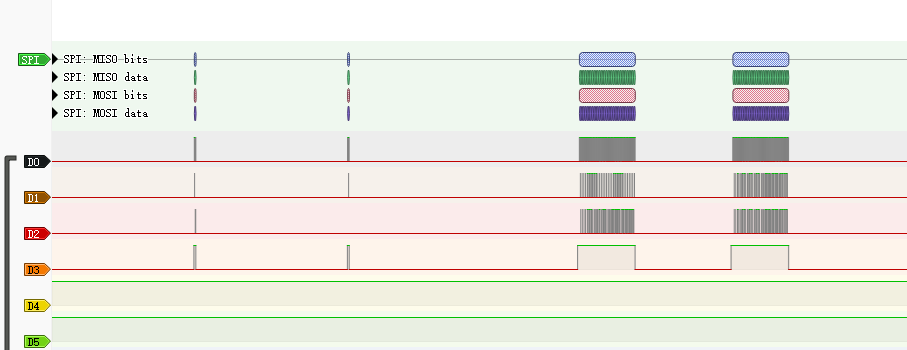
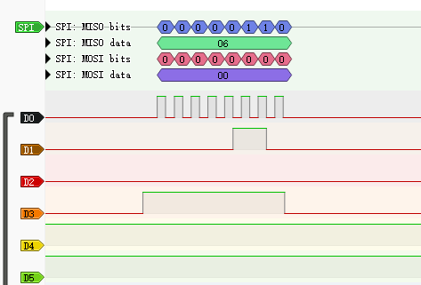
开始命令

回复命令
主机发送数据
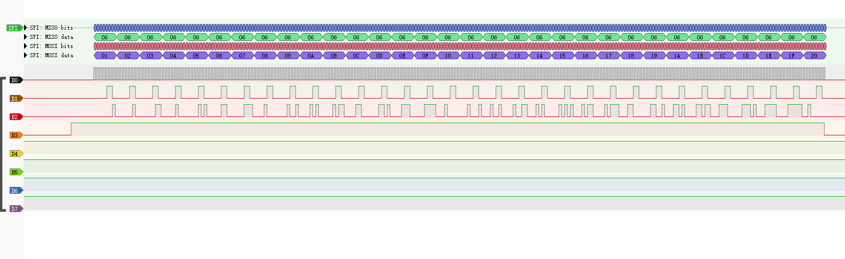
从机发送数据
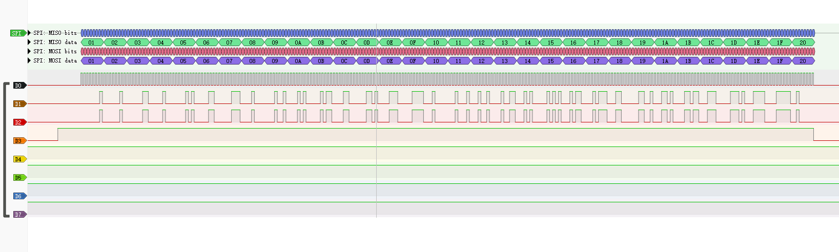
主机串口发送数据
![[外链图片转存失败,源站可能有防盗链机制,建议将图片保存下来直接上传(img-80tcTtL5-1660010618844)(https://raw.githubusercontent.com/Master-4869/pictures/main/image-20220809095442514.png)]](https://img-blog.csdnimg.cn/8a3b0fe2620d4255bb7005c94a3fff8a.png)
工程已经上传。工程文件
声明:本文内容由网友自发贡献,不代表【wpsshop博客】立场,版权归原作者所有,本站不承担相应法律责任。如您发现有侵权的内容,请联系我们。转载请注明出处:https://www.wpsshop.cn/article/detail/50760
推荐阅读


相关标签

