
热门标签
热门文章
- 1【树莓派】设置树莓派开机自动运行python脚本_树莓派开机自启动python程序
- 2消息队列ActiveMQ, RabbitMQ, Kafka, MSMQ等对比介绍_msmq和kafka
- 3Midjourney AI 绘制动漫人物_midjourney二次元人物 最好看的比例
- 4C语言判断链表中是否带环_c语言判断链表是否有环
- 5查询Linux服务器的配置信息常用命令_linux查看服务器配置命令
- 6前端Chrome浏览器下载文件采坑_浏览器控制台中的下载内容时间和什么有关系,下载过慢有什么解决方法
- 7Java---归并排序_java数组归并排序
- 8【STM32H7教程】第80章 STM32H7的QSPI 总线应用之QSPI Flash的MDK下载算法制作_stm32h7 qspi
- 9获取含有数字和大小字母的随机验证码(python)_python获取数字字母验证码
- 10对抗软件系统复杂性②:全局一致,统一隐喻
当前位置: article > 正文
一.对于stm32内部flash读写解读:_stm32f4 写flash
作者:odstu | 2024-01-31 14:11:31
赞
踩
stm32f4 写flash
对于stm32内部flash读写解读:
1.stm32其内部本身有一块flash其扇区分布:
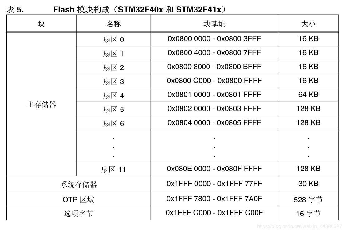
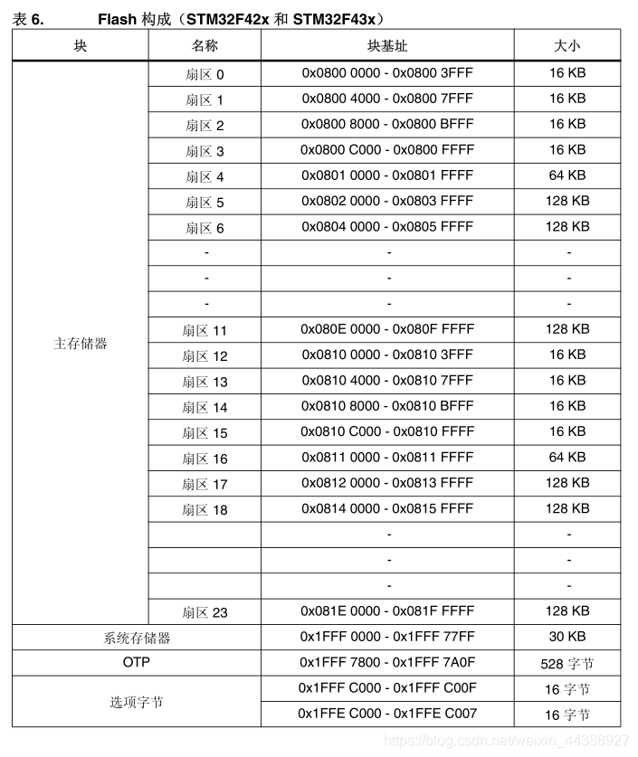
其中主存储去为数据存储区别:剩下的扇区则是flash内部一般不去改变的区域。
而对于内部flash的读写操作主要围绕主存储区展开。
以stm32f4为例,对于不同的芯片其大小是有区别的,但起始扇区却是固定的0x800 0000;
//为此可以在 xx_flash头文件中添加扇区起始地址的宏定义
#define ADDR_FLASH_SECTOR_0     ((uint32_t)0x08000000) /* Base address of Sector 0, 16 Kbytes   */
#define ADDR_FLASH_SECTOR_1     ((uint32_t)0x08004000) /* Base address of Sector 1, 16 Kbytes   */
#define ADDR_FLASH_SECTOR_2     ((uint32_t)0x08008000) /* Base address of Sector 2, 16 Kbytes   */
#define ADDR_FLASH_SECTOR_3     ((uint32_t)0x0800C000) /* Base address of Sector 3, 16 Kbytes   */
#define ADDR_FLASH_SECTOR_4     ((uint32_t)0x08010000) /* Base address of Sector 4, 64 Kbytes   */
#define ADDR_FLASH_SECTOR_5     ((uint32_t)0x08020000) /* Base address of Sector 5, 128 Kbytes  */
#define ADDR_FLASH_SECTOR_6     ((uint32_t)0x08040000) /* Base address of Sector 6, 128 Kbytes  */
#define ADDR_FLASH_SECTOR_7     ((uint32_t)0x08060000) /* Base address of Sector 7, 128 Kbytes  */
#define ADDR_FLASH_SECTOR_8     ((uint32_t)0x08080000) /* Base address of Sector 8, 128 Kbytes  */
#define ADDR_FLASH_SECTOR_9 ((- 1
- 2
- 3
- 4
- 5
- 6
- 7
- 8
- 9
- 10
声明:本文内容由网友自发贡献,不代表【wpsshop博客】立场,版权归原作者所有,本站不承担相应法律责任。如您发现有侵权的内容,请联系我们。转载请注明出处:https://www.wpsshop.cn/article/detail/50709
推荐阅读


相关标签

